Carburetor modification is required due to the fact that McCulloch supercharger system is a blow through system, requiring air to be blown through the carburetor and into the inlet manifold of the host engine. Consequently the carburetor becomes pressurized and it is necessary to seal all atmospheric vents, and all possible sources of fuel leakage, in order to maintain that pressure. The additional air being forced through the carburetor by the supercharger also results in the air/fuel mixture which is fed to the combustion chambers of the engine, being weakened, and consequently in order to maintain the correct air/fuel ratio during all operating ranges the jet sizes of the carburetor may have to be increased.
McCulloch instructions are reproduced for both general carburetor modification and more specifically for 1955 Holley teapot, and 1957 Holley modification. John Erb�s instructions for Carter AFB modification are also included, along with information provided by Dick Datson, and R2 AFB carburetor photos supplied by Jon Hardgrove of The Carburetor Shop. Hopefully there should be sufficient information here to enable successful modification of almost any kind of carburetor. Carburetor modification, and the amount of modification required, is a bit of a grey area, as different carburetor designs gave different modification requirements. As a rough guide however, newer carburetors tend to require minimal or no modification, as emissions control requires them to be air tight. Older carburetors require more extensive modification.
All of the carburetors that were available during the fifties, and probably all of their successors, can be modified for pressurization, providing that all internal chambers of the carburetor can receive an air supply from the air horn or venturi section of the carburetor. In other words, the carburetor must be internally vented so that the supercharger pressure, as it enters the top of the carburetor, can enter all the chambers within the carburetor and create an equal pressure throughout. If this internal venting is present, then plugging any external holes, in order to maintain the pressurization of the carburetor, will not cut off the supply of air to any chamber.
For those carburetors which are not internally vented it is sometimes possible to maintain the carburetion pressurization, and provide an equal pressurization throughout the carburetor, by running external air pressure lines to those chambers that cannot receive the supercharger pressure as it comes down through the air horn. As an example, if the float chamber is vented directly to the outside atmosphere rather than to the air horn, and this vent was plugged, thus resulting in a lower pressure within the float chamber than in the air horn, then if a separate air line was run from the carburetor bonnet to the float chamber, equalization of the float chamber pressure with the air horn pressure would be achieved. If this air line was not added, then because the air pressure within the air horn would be greater than that in the float chamber, no fuel would be able to be get into the carburetor for vaporisation, unless the fuel pressure was significantly greater than the air pressure within the carburetor. By pressurizing the float chamber, less fuel pressure is required to get the fuel into the carburetor.
As well as pressurising a carburetor for supercharging we need to make it function efficiently throughout the range from idle to full throttle with freedom from flat spots, and for it to perform with as good, or nearly as good fuel economy under cruise conditions as it would have done had the engine been normally aspirated. Naturally we should not expect good economy at full throttle, �high blower� conditions because the entire objective of supercharging is to force more air into the engine so that more fuel can be added, and therefore more power gained.
When considering carburetion the higher temperatures which will occur in the engines combustion chambers as the greater fuel/air charger is burned must be allowed for and kept in check, even though we are benefiting with additional horsepower. This can be achieved by maintaining a rich enough air/fuel ratio, however this should be balanced against possibly outrageous fuel consumption.
If fuel consumption at cruise was not a factor it would be a simple matter to merely enlarge the main jets excessively so that they would help out the enlarged secondary jets at full throttle and so. Furnish a rich enough mixture. However, this is also not a complete solution because the mixture at times would be too rich, and the engine would lose power whilst accelerating to �high blower�, full throttle condition where it would function very well. In other words, this solution would give stumbling, flat spots and high fuel consumption at most conditions under top speed.
A solution is to enlarge the power valve, so that additional fuel will enter the engine when it is under a heavy road load, but not under cruise conditions as would be the case were the main jets excessively large. However, this is not the best solution because, it too, can cause stumbling and flat spots by furnishing too rich a mixture upon sudden acceleration. This is magnified by the tendency of the power valve to open earlier on a supercharged engine because air pressure (even at low blower) acts on the diaphragm even as engine vacuum lowers and lessens it�s hold on the other side of the diaphragm. A modification of the power valve system is listed below in order to cure flat spots, caused by too rich a mixture, on acceleration from a closed, or partially closed, throttle.
Generally to modify a carburetor so that it is suitable for using with a McCulloch supercharger the following procedure should be followed:
Unfortunately the range of carburetors available, and more specifically the fact that I actually don�t have the necessary information, prevents me from listing detailed instructions for individual carburetors. However to further illustrate the above procedure I�ve included the two sets of modification instructions I do have, which are for the Holley carburetors used on the mid fifties Fords.
There is some debate as to whether it is necessary to replace floats with the solid Nitrophyl variety on low boost (5 -6 pound) applications. These can be difficult to obtain for some carburetors, and are probably not required, however my opinion is that whilst you are modifying a carb to accept pressurisation, you may as well modify the floats, to give you an extra insurance policy.
The options available for float modification are:-
1) Replace the floats with replacement solid Nitrophyl floats, which can stand up to 50-60 psi. The most straightforward method, assuming you can find suitable replacement solid floats for your carburetor. Duracon floats are available, but these are inferior to Nitrophyl and can fail as soon as boost reaches double figures.
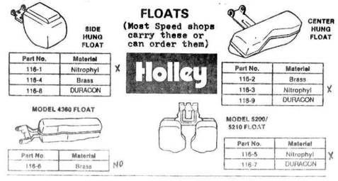
2) Modify Holley Nitrophyl floats to fit your carb. Holley makes Nitrophyl floats for many carburetor applications a nd it may be possible to find a match for the size of your floats, and then, as they have brass hinges, solder them to the hinges from your existing floats (Note - the blurred numbers in the above image are all 116- numbers).
3) Use expanding foam to modify existing brass floats. This involves drilling a couple of holes into the floats, filling the floats with the expanding foam, and then sealing the holes with a petrol resistant epoxy or plastic fuel, to prevent fuel from seeping into the float.
4) Drill two holes, opposing each other, in the middle of the floats. Insert a nail or thick wire through the holes, trim the nail, and solder up the ends to hold the nail and seal the floats back up.
Unfortunately we all don't live in an environment where it's warm enough for us to be able to remove the choke, and seal up the holes, thus preventing pressure leakage, and giving the added advantage of removing a restriction. Hence the following options are available for sealing the choke shaft.
1) If leakage is minimal - leave as it is - only air is leaked due to the choke position.
2) Try and "O" ring the shaft ends, and if the shaft is hollow plug the shaft ends with an epoxy.
3) Remove the choke cover for automatic chokes, and seal any vents.
Options available are:
1) If the throttle shaft has the linkage on one end then it may be possible to shorten the end without the linkage, and seal off the hole, or alternatively cement a sealing cap over that end of the shaft.
2) If drag can be minimised, "O" ring the ends of the throttle shaft, and plug hollow shafts with epoxy.
3) If drag is unacceptable, drill holes at one or both ends of the throttle shaft (depending on how many ends need sealing) as shown in the diagram, and feed air from the air horn to the drilled holes. As the air pressure is greater at the air horn than at the throttle, the fed air pressure will keep the air/fuel mixture from seeping from the throttle shaft.
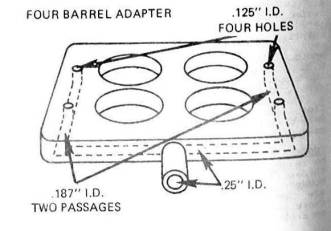
4) It is also possible to route the air pressure from the base of the carburetor, as shown in the Crane Cams diagrams above. The adapters used can be modified 1/4" to 1/2" spacer plates, or a more novel approach could be used such as the treated plywood adaptor made by Greg Meyers and desccribed on his site: http://cancermn.net/TS/TURBO.html . The Carter AFB made for the R2 Studebakers (see section below) is another variation of this theme.
Their has been much debate on the suitability of vacuum secondaries, and in all honesty mechanical secondaries are preferable to vacuum due to the fact that they require no modification � however vacuum secondaries have been and can be modified to work under blow through supercharging.
In the case of Holley carburettors secondary operation (under no boost) relies on a partial vacuum (actually low pressure) being generated in a vent that taps the primary venturii as a result of the flow of air past the vent. This low pressure pulls back the diaphragm that actuates the secondary throttle lever.
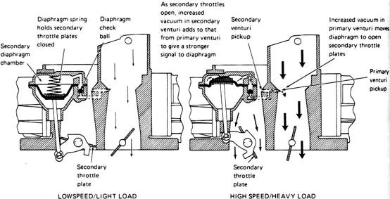
When under boost although the low pressure still exists it is actually at a higher pressure than the atmospheric side of the diaphragm � and consequently the diaphragm is not pulled back. To compensate for this the diaphragm needs to be boost referenced, i.e. the boost pressure at the carburetor air horn needs to be fed behind the secondary actuation diaphragm so that the original pressure differential is maintained. In the case of older (pre 57) Holleys this tends to be fairly straightforward as the throttle activation side of the secondary diaphragm is enclosed in a box. The vents to the box should be sealed up and a nipple attached to allow the lower part of the diaphragm to be boost referenced, as per the McCulloch 1955 Holley carburetor modification instructions detailed below. With later Holleys (4150 series onwards) no box is conveniently supplied, instead you need to work out a way of boost referencing the diaphragm. Possible methods are sealing the exit point for the actuating shaft from the diaphragm housing � either through O ring or some form of bellows type seal � which may require changing the diaphragm spring to compensate for the extra friction on the shaft movement, or encasing the bottom half of the diaphragm housing, the shaft, and the throttle lever within some form of box.� Once sealed a nipple can then be added to allow boost referencing.
Some Carters (Notably WCFB and AFB;s fitted to fifties Fords) use the same vacuum diaphragm setup as the Holleys, and accordingly should be modified for boost referencing in the same way. However the majority of Carters rely on manifold vacuum and air velocity via an air valve, rather than venturii vacuum to actuate the secondaries. The air valve opening rate which is dictated by air flow can be adjusted, dependent upon the carburetor model, via changing the springs (AVS and Thermo-Quad) or counter balance weights (WCFB and AFB). The addition of boost to the carburetor increases the air velocity quickening the opening rate (possible bogging), and consequently requires spring or counter balance adjustment to restore the original rate.

.
AFB carburetors can be used with at least 8-9 pounds of boost (some have been used with up to 18 pounds of boost, using solid floats) without the need for an air box, and were indeed sucessfully used in this way by Studebaker on their R2 engines. They are available with a large range of cfm capabilities, and can be found relatively cheaply.
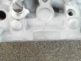
The Studebaker R2 carbs were modified by Carter to enable them to be used under boost. The main modification, as can be seen in the above photograph is that channels were cut in the base of the carburetor to connect the primary throttle shafts to the low pressure side of the carburetor, and grooves were cut in the throttle shafts where they met the channels. The reasoning behind this is so that the low pressure acts as a �vacuum cleaner� to any leakage across the throttle shafts, which is then fed to the secondary valve area.
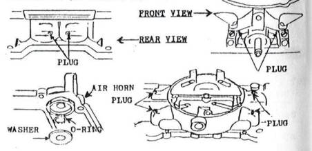
Carter sealed the idle needles on the R2 carburetor by �O� ringing them as illustrated by the above photographs. An indent (right picture, right hand side) was machined around the idle needle to seat the �O� ring, and a washer was used to hold the �O� ring and to provide a flat face for the adjusting screw spring. The floats had baffles inserted in them to prevent them from collapsing.
Gary Sypherd reports that if you are using a new or nearly new AFB, you don't need to change anything but the jetting up to 22psi(the point at which the floats collapse) and the accelerator pump seal. He found that the accelerator pump doesn't leak, nor do the throttle shafts, nor from any other "hole". Depending on horsepower, you may need to chage the inlet needle valves as they come stock from Edelbrock at .935" diameter. Edelbrock makes .110's and Carter has .120's
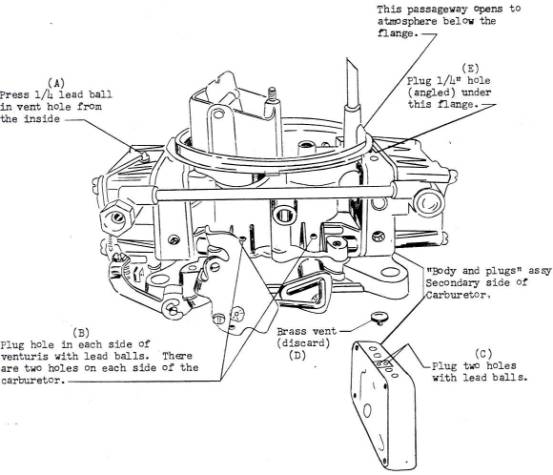
With the older AFB�s sealing of the carburetor is relatively straightforward, as can be seen from John Erb's procedure. Use Permatex No. 2 or other non-hardening sealer on the idle jet screw threads, venturi assembly retaining screws and the threads of the jet housing retainer screws.
1) The floats must be either replaced with solid floats, or modified to prevent them from collapsing.
2) Seal the accelerator pump shaft with an "O" ring, washer and epoxy as shown in the diagram. Alternatively Gary Sypherd reports that an easy way to seal the accelerator pump is the Edelbrock Marine Accelerator Pump Kit part #1471. This kit includes a new accelerator pump AND a factory engineered sealing washer with retainer! It is also US Coast Guard approved. No leaks, no fuss, no engineering, and it installed in less than five minutes!!
3) Plug all external vent holes with 1/8" lead shot, or equivalent. Do NOT plug an holes that vent ONLY air.
4) Enlarge secondary jet area 5% for each PSI of boost expected. Primary jets can often be left stock to get good MPG.
5) Enlarge the flow area around the fuel inlet needle and seats to increase the inlet flow capacity, if desired.
6) On automatic choke carbs, weld linkage to secondary throttle plates so that they MUST open at full throttle. Full throttle boost often holds them closed.
The following table lists 1950-56 carburettor jet sizes for supercharged engines, as recommended by McCulloch. 1957 applications, in the majority of cases, may well be the same, although I cannot confirm it. Unfortunately engines differ, and variations in the manufacture of the engine and carburettor, and the state of wear of both can lead to undesirable fuel economy, flat spots, etc. The carburetion modification instructions previously given are general, and cannot cater for all installations and host vehicles, and it is only through road testing that the correct jet settings, and ignition characteristics for an engine, can be determined.
Key:- NA � Not Applicable, NC � No change
|
Rochester |
|||||||
|
Car |
Year |
Main Jet |
Drill # |
2ndry Jet |
Drill # |
Power Valve |
Drill # |
|
Buick |
1956 |
.055 |
#54 |
.078 |
#47 |
NA |
NA |
|
Cadillac |
1956 1955 1952-54 |
.059 .055 .052 |
#53 #54 #55 |
.076 .073 .073 |
#48 #49 #49 |
.063 .063 .063 |
#52 #52 #52 |
|
Eldorado |
1955 |
.055 |
#54 |
.073 |
#49 |
.063 |
#52 |
|
Chevrolet 2B |
1955-56 |
.063 |
#52 |
NA |
NA |
NA |
NA |
|
Oldsmobile |
1956 1950-55 |
.063 .052 |
#52 #55 |
.086 .056 |
#44 #54 |
.063 .063 |
#52 #52 |
|
Carter WCFB |
|||||||
|
Car |
Year |
Main Jet |
Drill # |
2ndry Jet |
Drill # |
Power Valve |
Drill # |
|
Buick |
1956 1955 1953-54 |
NC NC NC |
NC NC NC |
.093 .086 .073 |
#42 #44 #49 |
NA NA NA |
NA NA NA |
|
Cadillac |
1955 1953-54 1952 |
.098 .098 .098 |
#40 #40 #40 |
.098 .081 .086 |
#40 #46 #44 |
NA NA NA |
NA NA NA |
|
Eldorado |
1956 |
NC |
NC |
NC |
NC |
NA |
NA |
|
Chevrolet |
1955-56 |
.096 |
#41 |
.067 |
#51 |
NA |
NA |
|
Corvette |
1956 1955 |
.089 .093 |
#43 #42 |
.055 .059 |
#54 #53 |
NA NA |
NA NA |
|
Chrysler |
1956 1955 |
.106 .096 |
#36 #41 |
.083 .070 |
#45 #50 |
NA NA |
NA NA |
|
�300� |
1955-56 |
NC |
NC |
.067 |
#51 |
NA |
NA |
|
Dodge |
1956 1955 |
.093 .073 |
#42 #49 |
.063 NC |
#52 NC |
NA NA |
NA NA |
|
Oldsmobile |
1950-56 |
NC |
NC |
.073 |
#49 |
NA |
NA |
|
Plymouth |
1955 2B 1955 4B |
.067 NC |
#51 NC |
NA .070 |
NA #50 |
NA NA |
NA NA |
|
Pontiac |
1955-56 |
.096 |
#41 |
.055 |
#54 |
NA |
NA |
|
Studebaker |
1956 1953-55 |
.093 .093 |
#42 #42 |
.067 .063 |
#51 #52 |
NA NA |
NA NA |
|
Golden Hawk |
1956 |
NC |
NC |
.082 |
#45 |
NA |
NA |
Holley |
|||||||||
|
Car |
Year |
Main Jet |
Drill # |
2ndry Jet |
Drill # |
Power Valve |
Drill # |
Power Valve Passageways |
Drill # |
|
Ford |
1956 2B 1956 4B 1955 2B 1955 4B |
.067 .055 .067 .055 |
#51 #54 #51 #54 |
NA .089 NA .089 |
NA #43 NA #43 |
NC .046 NC .046 |
NC #56 NC #56 |
.046 .046 .046 .046 |
#56 #56 #56 #56 |
|
Mercury |
1956 1955 |
.055 .055 |
#54 #54 |
.089 .089 |
#43 #43 |
.046 .046 |
#56 #56 |
.046 .046 |
#56 #56 |
|
Thunderbird |
1956 1955 |
.054 .055 |
--- #54 |
.089 .086 |
#43 #44 |
.046 .046 |
#56 #56 |
.046 .046 |
#56 #56 |
|
Lincoln |
1956 |
.063 |
#52 |
.101 |
#38 |
.046 |
#56 |
.046 |
#56 |
|
Continental |
1956 |
.063 |
#52 |
.101 |
#38 |
.046 |
#56 |
.046 |
#56 |
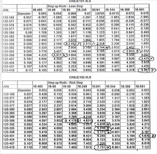
John Greenlaw generated this information on the primary rod/jet combinations required. The calc sheet shows the annular area around the drop rods in thousandths for various sized jets. Select a jet and drop rod, and where the column and row meet on the chart will be the annular area around the rod. Minus numbers indicate negative area, which means the rod is bigger than the jet.
To quote John Greenlaw: Roughly the larger the number, the greater the annular area, and the more fuel passed by the rod/jet combination resulting with a richer mixture. This is only a rough approximation, but it may help to whittle down selections more quickly. I have not checked every value by hand, but the ones I have are accurate. Some of the rod/jet part numbers are old; most are referenced to the Carter Strip Kit, Part No. 10-201. For comparison, I�ve created a table of some of the documented combinations. The Studebaker combinations are from the 1963 Studebaker Tune Up Standards, and the Summit combinations are from the January/February�95 Summit Parts Catalogue.
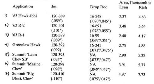
So what did I end up with? A little richer than stock R-1 (Studebaker). That�s not surprising. The real value of the sheet is that it gives a quick basis for comparing possible combinations. This table will work on other brands of vehicle than Studebaker, just not as well.