|
|
 |
Toyota 3MZ-FE V6 cylinder head modification
|
Here I will make various observations and comments on how the 3MZ-FE engine, transmission &c. function, and in some cases how to make improvements. New material will be added regularly, and eventually better organized. Click below to jump directly to an individual topic. |
Air inlet system
There is a two-stage air intake control system designed to boost performance across the range. The air cleaner inlet is divided into two areas, controlled by a vacuum switching valve and a butterfly-type air intake control valve. The air intake control valve closes one side of the air cleaner inlet when the engine is operating in the low-to-mid engine speeds.
A.C.I.S. system
The two-stage acoustic controlled variable induction system varies the effective intake runner length to maximise torque across the engines RPM range. This provides the benefits of long intake runners to boost torque in the low engine speed range, and short intake runners to boost power at high RPM.
The air control valve opens or closes depending on two variables: engine RPM and throttle position.
When the throttle body blade angle is less than 60°, the A.C.I.S. valve is always open regardless of engine speed, and at throttle blade angles greater than 60° with engine speed over approximately 4,000 RPM.
The A.C.I.S. valve is closed only at engine speed below 4,000 RPM and throttle blade angles greater than 60°. This increases torque at low rpm. The longer intake manifold (valve closed, VSV on) helps low rpm torque, shorter intake manifold (valve open, VSV off) helps the torque/hp at higher rpm. |
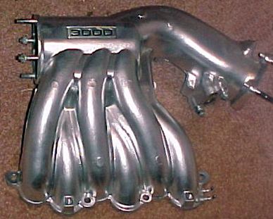
Intake manifold
The manifold and plenum are split horizontally into 2 pieces, a 1MZ upper manifold and plenum is shown here. Enlargement of the passages is difficult, not only to maintain a constant cross-section, but also the reduction in air speed affects low speed and partial throttle power and response. However, the alignment of the upper and lower sections | |
|
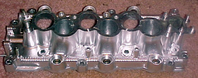
may not be as precise as we would hope, and some minor Dremel work here is worth doing. Don’t enlarge anything, just align the parts as best you can, then match the smaller ID to the larger using a gradual radius and blend the cut into the existing surface. Here’s the lower manifold showing the passages to be matched. | |
|
Some internal improvement can be made at great expense by using the “Extrude Hone” process, which forces a high-viscosity abrasive slurry through the ports under pressure. This cannot change the direction or area of the passages, but it does remove casting flaws, minor surface irregularities, &c. and has no ill effects (except cost!). Both upper and lower sections should be attached to make best use of this process. Click here for details on having your manifolds done:  . .
For increased high RPM power (and potential power loss below it) the plenum can be enlarged to add volume. This is especially helpful for turbo applications, where the combined volume (everything between the compressor discharge and the runner entries) can be as large as 150% of engine displacement, or 4,965cc (303 cubic inches); this can be a cylinder 5” in diameter and 15” long. Although the shape is not critical, the length should extend past the last runner entry at each end by at least one runner diameter.
This is frequently done by cutting the plenum apart through one plane, and splicing in a section of wall to extend one dimension. A more complex method is to remove the existing pleum entirely, and substitute a larger cylinder or box with suitable modifications for the runner and throttle body entry points. Care must be taken to retain the original position and clearance of the throttle body entry, &c.
Peak torque RPM can be raised, which raises peak power and peak power RPM as well (and potential power loss below it) by shortening the manifold runners. This is frequently done by severing the plenum and relocating it to a new position farther down the runner length, or cutting the runners off from the base and removing a section. This will change the position of the throttle body, &c. |
Porting
Porting generally refers to selective metal removal in the head, specifically in the area between the valve seat and the lower intake manifold gasket surface; the intake port begins where the intake manifold ends; in fact, the entire passage from the plenum to the valve is all port.
Porting is best left to professionals with experience with these engines (or a flow bench), but there are some areas where careful, precise work can be done by those with no technical experience. Do not attempt to straighten or re-align the port, or bias the flow in what may appear to be a more favorable direction. Porting work cannot be done until after head milling (if any), final valve size selection is complete and valve seats have been cut.
The bowl area (the part of both the intake and exhaust ports immediately above the valve seats) is generally not fully finished and contains casting irregularities and a certain degree of mis-match between the machined valve seat and the as-cast port area. Enlarging the bowl to match the valve seat bottom relief cut ID, and blending the bowl into the port is recommended.
The port contains some casting roughness, which should be blended into the wall surface. Leave the intake wall surface coarse and grainy, but polish the exhaust wall surface.
Matching the head’s intake ports to the manifold ports is recommended. They must be made the same size or slightly larger (never smaller) than the manifold ports. Don’t use a gasket as a template unless you’re sure it’s very close to the port size. A 6 long-stemmed carbide bit will allow the slight enlargement to be blended up into the port runner. Don’t go beyond the gasket outline or attempt to polish the surface.
The intake guide boss can be narrowed by removing material from both sides only, leaving the length intact. Taper both sides with the long axis aligned with the gas flow.
This will roughly follow a line between the guide center and the port center. Making it teardrop shaped, with the leading (port) end rounded and the trailing (bowl) end in a smooth point.
This streamlines the guide, directing gas more easily around it with less resistance and flow disturbance, by using the remaining boss to direct gas around the valve stem and guide.
The exhaust guide boss can also be narrowed by removing material from both sides only, leaving the length intact. Taper both sides with the long axis aligned with the gas flow. Make it teardrop shaped, with the leading (valve) end rounded and the trailing (manifold) end a smooth point - the same shape as the intake boss, but with the direction reversed.
The exhaust ports can also be matched to the iron exhaust manifolds or header flanges, but it’s important to leave the head port openings slightly smaller (never larger) than the manifold or flange opening. The port surface can be polished if you wish, but a satin (smooth, but non-reflective) finish is sufficient.
Both intake and exhaust ports can be slightly widened on both sides beginning just before & ending just after the valve guide to make up for the loss of port area caused by the intrusion of the valve stem and guide. This will produce an elliptical shape (from the original roughly round cross-section). A depression about 1/16-3/32 deep can be cut or ground in each side of the port wall, centered on the valve stem, and tapering off ¼-½ in both directions to blend in with the existing wall; a deeper cut would be more effective, but I’m not sure how close the water jacket is at this point - try a junk head first if possible.
The port cross-section is now elliptical at the valve stem location, stretching the sides to increase the area only where the valve stem and guide boss intrudes into the flow. This must be done very carefully, or not at all.
The heads can be modified by Extrude Hone. This is not nearly as effective as professional porting, and very expensive; click here for details on having your heads done: .
Valve sizes can be increased, although this is expensive. 35mm (1.378”) intake valves and 27.4mm (1.079”) exhaust valves have been successfully fitted to the 1MZ engine with its smaller 87.5mm bore. This size will work even better in the 3MZ since the cylinder wall is 2.25mm (.089”) farther away, which un-shrouds the valves nicely.
|
Exhaust manifolds
The original manifolds are fairly efficient, and replacing them with fabricated steel tubing is not cost effective for any but the most highly developed engines. The trade-off in exhaust heat, labor, life expectancy &c. is expensive.
However, the manifolds can be substantially improved by porting. This means enlarging the entry openings (where the manifold bolts to the exhaust ports in the head) to or slightly beyond the gasket size, and re-contouring the passages as deeply into the manifold as you can reach. This has the advantage of retaining original appearance and fit.
Begin with a clean gasket surface on the manifold. Cover it with a layer of masking or duct tape; use a rolling pin, &c. to make sure it’s firmly attached. Take an exhaust gasket of the same type as the manifold (used, in good condition OK), and very carefully position it on the manifold, being certain to line up the bolt holes all around. Trace a line following the inside port surface of the gasket on all three ports. Cut through the tape along this line using a single-edge razor blade, &c. Carefully peel back the tape inside the port opening, and discard. The remaining tape will offer good protection against accidents. If you prefer, use Dykem, &c., coating the top surface as per product directions.
Spray paint may be substituted - lightly spray the top surface from directly above. Wait 5 minutes, and then remove the gasket. With Dykem, you now have a line separating the area needing work from the area that will be left as-is for now. If paint is used, only the painted area should be cut. You may still find it useful to apply duct or masking tape to the gasket surface to protect it from accidents. The area inside the gasket is not the absolute limit to the modification, but it’s a safe place to stop.
Remove metal with the carbide bit, using smooth strokes, from the edge of the existing port opening. Don’t try to get the whole bit into the port - a 45° angle is fine. Work right to the edge of the tape (or paint, &c.). Do the next port; don’t worry about the passage itself yet. Once one manifold is done to the tape line, do the other one.
When trying to decide how extensive to make your openings, remember that it is easier to remove metal than to put it back! If not sure, stop at the edge of the gasket marks. The most common mistake is doing the 1st few ports to the max, and not having the patience to do the remaining ones to match it.
Any porting at all is a big improvement, and the first metal you take off has the greatest effect.
After you’ve gotten this far, you can try extending the new size deeper into the passages. Some will be easier to do than others, and some will obviously need more work. Be careful to note where any bolt perches intrude into the port shape - you can’t remove all the metal here, or it may crack when tightened. Just smooth the metal leading to & from the boss as much as possible. Remove any obvious casting flaws, parting lines, &c.
The longer-stemmed 6 bits allow you to go deeper into the passages. Keep the speed down, as the length will cause chattering when pressure is applied.
After doing all six ports, carefully inspect all passages for gouges, roughness, &c., and re-do problem areas. Are all port openings done equally? If you’re satisfied here, this is a good place to stop. Remove the tape or paint, and blow out the manifolds with an air hose.
If you want to be a bit adventurous, more improvements are possible. The port can be opened wider & taller than the gasket limit to some extent. If you go too far, the gasket won’t seal properly. However, at least 1/32 can be safely removed from all edges (total of + 1/16 in width & height) is safe in most cases. This does not have to extend into the passage to have an effect - a 45° bevel is enough to form a reversion step. Do not taper, blend, or bevel the manifold opening to act as a transition between the exhaust port and the manifold.
The improvement is not only a bit less restriction, but also a one-way valve for exhaust gas. Gas flows out almost as well as before, but at low speeds the sharp ledge confuses gas trying to back-flow into the port again during overlap.
The manifolds can be modified by Extrude Hone, although in my opinion the manifolds’s shapes and sizes are not so complex that an enthusiast cannot do an acceptable job here (which is not true for the intake manifolds); click here for details on having your manifolds done: .
The stock “Y” pipe (where the two manifold outlets join) is not very good, and an aftermarket pipe is a nice improvment here.
|
|