|
|

|
| ||
|
|
After the original introduction (limited to Chrysler cars only), DeSoto developed and introduced its own unique hemi motors in 1952, which I will refer to as Type II. These motors were smaller than the Chrysler hemis by virtue of smaller bores, closer spacing of the bore (the distance between adjacent cylinders in the block), main bearings & cam bearings, shorter strokes and lower engine block cylinder banks. After the original introductions, Dodge developed and introduced their own unique hemi motor in 1953, the Type III. These motors were smaller than the both the Chrysler and DeSoto hemis. In 1964, Chrysler introduced yet another hemi motor (the largest: Generation 2) developed from the “RB” and unrelated except in general theory to the earlier types. Because of these differences, almost no major parts can be interchanged between brand names or “families”. In the Chrysler literature, hemi motors are also called dual rocker shaft (“DRS”) while poly motors are called single rocker shaft (“SRS”). No Plymouth used a hemi motor until 1964.
|
|
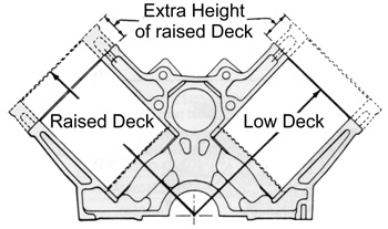
The DeSoto raised deck motors had their tappet bank angles re-aligned from 64° closer to vertical to 60° to align the tappets with the new (higher) rocker arm positions and maintain proper valve train geometry. The other Types also used different tappet bank angles for their low deck vs. raised deck engines.
| |||||||||||||||||||||||||||||||||||||||||||||||||||||||||||||||||||||||
| ||||||||||||||||||||||||||||||||||||||||||||||||||||||||||||||||||||||||||
Valve Train The hemi motor’s tappets and pushrods are accurately “pointed” at the rocker arm ends for best mechanical efficiency. The intake and exhaust rocker arms are different in length, and pivot in opposite directions. A true hemisphere is a 50% segment of a full sphere (width = diameter, depth = radius), but the DeSoto hemi’s combustion chamber shape is not a “mathematically correct” hemisphere but a partial section, since the chamber depth is less than the radius of the theoretical sphere, and the chamber width is less than the diameter of the theoretical sphere; the theoretical sphere being the shape from which the actual curvature of the chamber wall is taken. Although aesthetically pleasing, the DeSoto’s deep chamber (where the depth is a large percentage of the radius, although less than 100%) has proven not to be the most efficient shape, and later motors (such as the “RB” based 426 hemi) used a lower percentage of a hemisphere of larger diameter. Generally, the width of the chamber is equal to or slightly less than the bore diameter; this provides room for the largest valves. However, chambers of smaller diameter (but not larger) can and have been used successfully. The hemispherical shape has the lowest “surface to volume ratio” of the possible choices. This means that the amount of heat and energy lost by contact with the surface of the chamber is smaller than any other practical shape with the same volume. This factor was given more importance at the time than is held by current opinion, which favors more shallow chambers. The hemi combustion chamber shape is also conducive to intake flow from the valve seat, as the chamber wall offers less obstruction than most other choices. However, the large chamber volume requires a large compression dome on the piston to achieve a high compression ratio. This dome adds to piston weight, obstructs port flow when the piston is near TDC, obstructs flame travel, and loses back part of the surface to volume advantage referred to earlier. This is one reason why the hemi is more successful in supercharged and turbocharged applications than normally aspirated: the smaller and lower piston dome for the 8-1 compression ratio (favored for boosted operation) is less of a problem than the tall and irregularly-shaped dome on a 12-1 piston. In a “wedge” motor, the intake valve stem angle is inclined at only 6-23° from the cylinder bore axis, while the intake port is nearly 90° from the bore axis, so the intake port shape must include the remaining 67-84° curve, which reduces flow. Since in a typical wedge motor the intake and exhaust valve stems are parallel, the wedge exhaust valve is inclined against its port flow direction, so the port curve is closer to a 96-113° curve (this is not as critical since the exhaust flow is under pressure). Hemi valves have an “included angle” (between the two valve stem axes) of 53°. Each valve is inclined favorably from the bore axis by 50% or 26.5°, so the port curves are reduced to only 63.5° (the valve stem more closely follows the direction of the port centerline), and flow is improved. As a note: there is another chamber design variant in which the valves are not parallel to each other, but the shape is not a hemi. This type includes the Chrysler, Dodge and Plymouth “poly” motors (331, 270, 318, etc.), Chevrolet big block (396, 427, 454, etc.), Ford Cleveland & Boss small blocks (302, 351, 400), and Ford 385-type big blocks (429, 460). The valve stems in these motors are inclined both to the bore axis, and to the other valve. The intake and exhaust valves were located on opposite sides of the chamber at 90° to the cylinder bank (directly across from each other), so separate individual rocker shaft assemblies (two on each head: intake and exhaust) were necessary for all valves to be controlled by the same camshaft. The tappets (lifters) were placed in left and right banks to align accurately with the rocker arm ends. Both intake and exhaust pushrods closely follow this angle, which insures optimum mechanical efficiency and minimal lost motion: there is almost a straight line between the cam lobe, the tappet, pushrod and rocker arm. The pushrods enter the heads at approximately the same place, but the rocker arms operate in opposite directions: the exhaust rockers pivot out towards the exhaust valve stems, while the intake rockers pivot back in towards the intake valve stems. Since the pushrods’ point of entry into the head is nearest the intake valve, the exhaust rocker arms are longer and heavier. In theory, the hemi head design permits better port location and alignment (compared to a wedge motor). The intake valves can be inclined to improve the “down-draft” angle of the port (as in a wedge), but the exhaust valve can be separately positioned to incline more favorably to the exhaust port (in this case, 26.5°, an improvement over the 6-23° reverse-inclination of typical wedge exhaust valve). A disadvantage of the hemi valve arrangement from a thermodynamic point of view is that the combustion chamber shape does not offer flat surfaces to the piston dome to form “squish” or “quench” areas to provide turbulence and knock suppression. In a low compression motor using a flat-topped piston, which does not rise above the cylinder @ TDC, the shape is acceptable where cylinder pressure is low to moderate. This not only limits the motor’s compression tolerance considerably, but also makes the dome shape of a high compression piston asymmetrical and complex, as the dome must fill part of the chamber @ TDC but not touch, or even mask, the intake or exhaust valves or spark plug. The valve seats are located directly across the head from each other and 90° to the bank axis, not parallel to the cylinder bank axis (as in a wedge). All original pistons are cast aluminum alloy. Most have slight compression domes (area of slightly smaller diameter than the bore) with two valve clearance notches. All have floating piston pins with retaining clips. Pistons are marked for direction, as the piston pins are offset to the rear; be careful to follow the instructions for which way the mark goes - usually towards the front of the motor. The engine blocks are excellent quality of design, material and workmanship. All were two bolt main cap types, meaning the crankshaft main bearing caps securing the main bearings to the bottom of the block used two bolts for each cap. Each engine family, stroke length and deck type has its own unique rod. All rods are high quality forged steel, and more than adequate in strength for the original power produced. No crankshaft other than DeSoto can be used in a DeSoto motor. All crankshafts are high quality forged steel with rolled fillets, and use an un-threaded 8 bolt (obsolete pattern) flange. More importantly, the pre-1962 flange for the 1956-61 A-466 iron Torqueflite protrudes farther out of the block than the 1962-* flanges. This precludes direct use of a later transmission or bellhousing, as the crankshaft is too long, and a 1962-* A-727 Torqueflite bellhousing will be short of the correct position and require an adapter. | ||||||||||||||||||||||||||||||||||||||||||||||||||||||||||||||||||||||||||


(Click here for the next page)
See these Victory Library booklets | |||||||||||||


