|
|

|
| ||
|
|
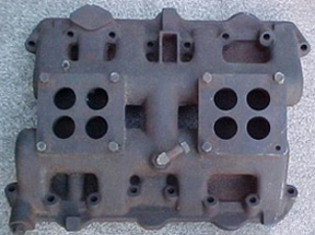
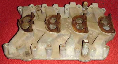
Normally, a single carburetor will be a 4 bbl., either the older Carter AFB/AVS or newer Holley. The motor is not unlike other V8 engines, and doesn’t have special preferences; whatever brand and model you have personal experience or past luck with is fine. The size for performance street use should be roughly proportional to engine size, not maximum power. As a rough guide, you can effectively use between 1.5 and 2 CFM per cubic inch; a 276 will feel good and perform well with a 500 CFM carburetor, a 345 can use a 650, etc. Bigger is not better here; you won’t feel any difference in maximum power unless the carburetor is much smaller than you need, 50 CFM one way or the other doesn’t matter. For the 276-291 motors, the Carter AFB for the 273 “LA” is a good choice, as well as the Rochester 4GC for the BOP aluminum 215 V8 & Buick 300/340. The exception to this rule is the spread-bore type, where the primary barrels used for normal driving and cruising are intentionally much smaller than the secondary barrels, which are only used at nearly full throttle. Most of these also have demand-sensitive secondaries, which only open when the motor needs extra air. I like the QuadraJet (GM), which was factory-installed on motors as small as 231. They’re easy to find and tune, inexpensive to purchase used, and provide excellent low speed and part throttle response for their size (750 or 800 CFM). However, the bolt pattern (also found on ThermoQuad and Holley 4175) is not common to any original poly manifold, so an inexpensive adapter is needed - this will add ½ of height. The carburetor of choice for many years was the Stromberg 48 & 97, which have a 3-bolt base flange bolt pattern. However, these are now relatively rare and expensive, and don’t flow as much air as more modern replacements. The Rochester 2G, 2GC & 2GV (as used on Chevy 348 & 409, Cadillac Eldorado, Olds 442 & J2, and Pontiac tri-power) are common on V8 motors from the 1960s and 1970s, much less expensive (used carburetor on eBay: $10.), easier to tune & repair, and available in five sizes, all of which have higher air-flow capacity than the Strombergs. The 2G small bolt pattern is 3¼” × 1-7/8” (also referred to by its SAE flange size of 1¼”); the large bolt pattern is 3¾” × 2” (SAE flange size: 1½”). They’re easily modified to increase CFM by the usual methods. Get the “Rochester Carburetors” by Doug Roe for a complete guide to jetting and adjustment. Be sure to get the model with the side-mounted fuel inlet for clearance in between the carburetors. The primary (center) carburetor can be up to three sizes smaller than the two end carburetors for best idle quality, part-throttle response and gas mileage. Don’t use a velocity stack; the best air cleaner is a late-model V8 high-performance can with snorkels, and a K&N filter element. Run a large diameter hose from the snorkel to the radiator support and get cold air to the carburetor - it’s worth quite a bit of power. If you don’t mind hot air reaching the carburetor, a Moroso, etc. 14 × 4 (or the tallest one that clears your hood) open-sided can assembly is fine.
| Modifying the DeSoto Hemi Motor for High Performance The key to making any motor perform is not a single piece of speed equipment or major design change, but a large number of small, subtle and relatively minor changes that are co-ordinated to work together and reinforce each other’s effects. Luckily, many of these are inexpensive and only require time and labor, rather than money.
| |||||||||||||||||||||||||||||||||||||||||||||||||||||||||||||||||||||||||||||||||||||||||||||||||||||||||||||||||||||||||||||||||||||||||||||||||||||||||||||||||||||||||||||||||||||||||||||||||||||||||||||||||||||||||||||||||||||||||||||||||||||||||||||||||||||||||||||||||||||||||||||||||||||||||||||||||||||||||||||||||||||||||


The original distributors all used points (Kettering system), some had dual points. They can upgraded by either using a drop-in electronic replacement such as Pertronix, or simply use a Chrysler “LA” electronic distributor, which is a drop-in for all poly “A” and Dodge low deck motors. Other motors have are some shaft length differences, and adapters and converted distributors are available commercially; see the Source Table.
It’s possible to adapt a GM HEI to the original poly distributor; it’s been done with the points-type “LA” distributors. For those even considering EFI as a future project, HEI offers additional compatibility with GM harnesses, etc. for conversions using modern OEM EFI parts.
The mechanical (centrifugal) advance curve (present in all distributors) is not too far away from what I would suggest for a hot street motor. The initial advance setting should be between 10° and 15° BTDC, with the final adjustment to be made after the motor is started. Larger motors and hotter cams will prefer the higher (15°) setting, heavy cars and warm temperatures prefer the lower (10°) setting. The centrifugal advance curve should add 20° to 25° to give a total of 35° as a good place to start. The curve should be complete (fully advanced) by 2500 RPM. Any distributor shop can do this if your distributor has the wrong curve.
The vacuum advance diaphragm and mechanism should be retained, and repaired if not functioning properly. At any throttle opening except idle and full throttle, vacuum advance provides better part-throttle acceleration, keeps spark plugs cleaner, reduces engine temperature, improves gas mileage, and lowers oil temperature during cruising.
Even some race cars will drive to the staging lane and return better, with less plug fouling, with the vacuum advance adjusted to add only 5°.
If the motor knocks or pings under part throttle operation, but the ping disappears under hard throttle, your vacuum advance is staying on too late, or too far. The “LA” distributor’s vacuum can is adjustable. There are alternate part numbers for vacuum mechanisms, but very few will still be available, unless the “LA” parts can be adapted (no information here).
If the motor pings under hard throttle and moderate RPM (without vacuum advance), try slowing up the advance curve (heavier spring) to give full advance at a higher RPM; try 2700.
Individual motors will like different settings based on compression ratio, cam timing, air and water temperature, gas quality, gear ratio, chassis weight, stall speed, etc.
Almost all motors will be happy with only 10° initial advance and a 25° advance curve (total: 35°), but more initial advance (15° + 20° curve = 35°) will have cleaner idle, feel “sharper” and give better part throttle power, but may ping at low speed and hard throttle.
Here are some factors that cause ping and knock, and require either high octane gas, less spark advance, or both:
» “loose” piston to head clearance (.060” or more)
» “tall” 1st gear ratio (Powerflite)
» high vehicle weight
» 195° thermostat
» lean mixture
» hot spark plugs
» tight converter with low stall speed
» higher (lower number) axle ratio
» high initial ignition advance
» fast advance curve
» weak spring in vacuum advance canister
Boring and honing should be done with a torque plate. The finished bore shape is influenced by head bolt tension, and will be out of round when assembled if a plate is not used. The greatest effect and benefit of a torque plate is to imitate the distortion caused by the head bolts, so that the boring bar follows the same shape that would be present in the block when assembled (although a lesser effect is the rigidity of the head casting).
It’s almost impossible to find a DeSoto torque plate, but I have a thought that may prove useful (although it hasn’t been tried on these motors). If a plate is not available, another method may be used to distort the block: accurately measure the depth of the head casting at each head bolt location, and record it. Make ten steel spacers (one per head bolt) with the same thickness as the depth of the bolt hole, 1” wide (or as wide as will not obscure the bore opening), with a through-hole for the head bolt. The length of the engaged thread is important, so measure carefully. Insert the head bolts through the spacers and apply the correct head bolt torque. Make sure the bore is completely open (no spacers hang over the edge). Leave the bolts in place until honing is complete. Don’t use any larger bore size than you need to get a perfect hone pattern. The added displacement is very small, and in some cases the rings don’t work as well with larger sizes, since the remaining cylinder wall is not rigid enough to retain its shape under load, causing poor ring seal, blow-by, oil consumption, etc.
The piston choices for DeSoto hemi motors (stock and stroked) are not very good, since the bore sizes are small and no longer common. The compression distance, dome volume and piston pin diameter are all important. If the piston’s pin size is too small, the rods can be bushed down. For any stroke and rod choice, the piston’s compression distance should be calculated to achieve .000” deck clearance @ TDC.
The formula for compression distance is:
C-Dist. = Deck Height - Rod Length - ½ Stroke Length - Piston Deck Clearance
The hemi blocks had generally thicker cylinder walls than modern motors, and many can be safely bored to +.090”. The following Table shows engine displacement for most common bore sizes and possible stroke lengths. These bore sizes are not recommendations that a specific bore size is practical, or even possible - that must be your own decision. For bore sizes in between sizes listed, interpolate to get displacement.
Most custom piston manufacturers will be happy to furnish a set of pistons in any bore size, piston pin diameter, ring stack, and compression distance you want. However, I suspect that the dome shape required by the deep combustion chamber of the hemi motor may require special instructions, especially for a high compression piston. Expect to spend money on this.
Because of the rarity of the block, don’t use any larger bore than you need to get a perfect hone. Any custom piston is available in irregular oversizes (+.025”, etc.).
If a stroker crankshaft is not found in the exact stroke length you require, the piston can be chosen first, and the exact stroke length selected by calculating backwards to make a common and inexpensive piston useful.
To calculate stroke length from a known piston:
Stroke Length = 2 × (Deck Height - Rod Length - C-Dist. - Piston Deck Clearance)
Any commercial piston not specifically intended for a hemi motor will have valve notches in the wrong place, and must be re-notched to match the valve positions when partially open near TDC on overlap. Both the intake and exhaust valve open at a more acute angle than a wedge motor. When the reliefs are finished, radius all edges 1/16” and blend into the dome surface - don’t worry about adding a few CC to the chamber volume. This work should be done before balancing, the amount of metal removed made identical on all pistons, and the volume (CC) recorded and added to the total combustion chamber volume when calculating the compression ratio.
It is extremely important that the piston’s position @ TDC is at .000” (-.010” acceptable). This gives a final deck clearance equal to the head gasket thickness, typically .040”. If this figure is larger than .060”, the advantages of quench disappear. I strongly suggest that you make every attempt to achieve this, as this single step is an important improvement in the way the combustion chamber functions.
“Stroking” simply means increasing the distance that the rod journal centerline (where the big end of the rod rides) is offset from the main journal centerline (what the crankshaft rotates on). The stroke length is twice the offset: offset up = TDC, offset down = BDC.
Main journal size, rod journal size, rod length and deck height do not affect stroke.
Any stroked motor must be re-balanced.
It is generally possible to weld and “offset grind” the rod journal to increase the stroke. This is done by only adding metal to the outer (offset) side of the journal, then grinding the journal back to original size by removing more metal from the inside (original surface), which moves the centerline away, increasing stroke.
Another method is to weld the rod journal all around to the larger diameter of a different rod, and re-grind to the new rod’s journal size. The rod’s other dimensions must be suitable: width of the bearing, length and pin diameter. This sometimes allows three simultaneous advantages:
1. gives a slight stroke increase (equal to the difference between the rod journal sizes)
2. allows a more modern, or stronger, or different length rod to be used
3. does not reduce journal overlap (see comments below)
There are three major areas of potential interference between the crankshaft assembly and the block in stroker motors.
1.
This is the point where the rod “shoulder” (side of the beam) strikes the bottom of the cylinder wall, typically somewhere in mid-stroke. Any motor with a longer stroke, or longer rods, or both, will need additional clearance ground or machined in the lower edges of the cylinders (total of 16 places), on the stroke axis (90° from the bank axis). Metal must be removed from the block so that the rod beam passes with at least 1/16” clearance at any point. This is made worse by any combination of these factors:
a. Longer stroke
b. Longer rod
c. Heavier rod construction (“H beam”, aluminum rods, etc.).
If interference occurs, grinding a notch slightly wider than the rod beam in the bottom of the cylinder opening may cure it, but there is a limit to how much metal may be removed before you perforate the water jacket between cylinders. This limit is not only varies between different motor types, some (to a lesser extent) between individual motors of the same type, and even between different cylinders in the same motor, so be careful.
2.
The second area of interference is the outer diameter of the counterweights. The crankshaft must (obviously) be free to rotate, and the “swing” of the largest weight must clear any part of the block by 1/16”. If the counterweight is too large, some clearance grinding inside the block will help, but in many cases the OD must be reduced; turning it down in a large lathe is the preferred method. This should be done before any journal grinding is done, so that any distortion caused by the lathe operation is normalized by the final grinding.
Don't just cut the counterweights to the OD of the original crankshaft, since (although obviously safe) it may not be as tight a fit as possible - try rotating the original crank with pieces of clay on the counterweight OD of various thicknesses. Turn it over very slowly, and see which pieces are gone, which are scraped down, and which are still untouched. Since this only removes material from the balance weights, the crankshaft will be badly out of balance afterwards, so this must be done before any balancing work, and will make balancing more difficult and more expensive.
3.
This is the point where the big end of the rod strikes the oil pan rail or the inside of the block. This is controlled by slightly different factors than 1. (above). Increasing any of these makes the problem worse:
a. Larger rod journal offset (= ½ stroke length)
b. Larger rod journal diameter
c. Larger rod big end size and shape
As any of these increases, the outer edge of the rod’s big end moves towards the block. Reducing the journal diameter without changing the stroke increases the clearance; this assumes that the new rod is proportionate to the smaller journal, which is generally true but must be measured.
To test: if you have the old crankshaft, try to rotate it with a piece of clay on the journal substituting for the rod's big end (so you don't need to assembly the crankshaft). If you rotate it slowly, the clay will squash to a safe distance. To calculate the maximum component size from this:
Add ½ stroke length + ½ journal diameter + clay thickness + 1/16”.
The total of ½ new stroke length + ½ new rod journal + thickness of new rod big end from ID to OD must be no larger than this.
All of the original rods are high quality forged steel parts, but probably need rebuilding. This is a straight-forward operation that can be done by any competent shop. I insist on using ARP rod bolts. If you wish to polish the rod beams (not necessary, in my opinion), they should be shot-peened afterwards to restore the “skin” (more dense surface left by forging). Piston pin oiling can be slightly improved by drilling a 3/32” hole vertically through the very top of the rod eye. Radius the entry carefully, remove any burrs inside the pin bushing, etc.
I suggest you explore some possible alternate rod choices (following Page) before making any investment in your old rods. Any rod other than the original may not have the same piston pin diameter, which means either re-fitting the rod (where possible: either reaming to a slightly larger size, or bushing to a slightly smaller size) to the piston pin size of the piston you will use, use the piston intended for the new rod, or a custom piston.
Hemi Deck Type Vs. Crankshaft Data | ||||||
Size | Deck Type | Stroke | Main Journal | Rod Length | Rod Jrnl. | Rod Width |
330, 341, 345 | Raised | 3.800” | 2.500” | 6.625” | 2.250” | .931” |
276, 291 | Low | 3.34375” | 2.375” | 6.067 | 2.0625” | .937” |
Alternate Rod Data (Sorted by Journal Size) | |||||
Motor | Year | Size | Length | Rod Journal | Rod Width |
Chevrolet | 1955-67 | Aftermarket for 327, etc. | 6.250” | 2.000” | .940” |
6.125” | |||||
6.000” | |||||
5.850” | |||||
1968-* | Aftermarket for 350, etc. | 6.250” | 2.100” | ||
6.125” | |||||
6.000” | |||||
5.850” | |||||
”LA” | 1964-* | 273, 318, 340, 360 | 6.123” | 2.125” | .935” |
Buick | 1967-76 | 400, 430, 455 | 6.607” | 2.250” | .928” |
Oldsmobile | 1968-* | 400, 455 | 6.735” | 2.500” | .925” |
1965-67 | 400, 425 | 6.998” | |||
As the stroke length is increased, overlap is reduced, unless one or both journals is increased in size. There is no absolute minimum figure, but compare the numbers for some motors in the Tables. The formula for journal overlap is:
Journal Overlap = ½ (Main Journal Diameter + Rod Journal Diameter - Stroke Length)
Crankshaft Journal Overlap Data | ||||||
Deck | Size | Main Jrnl. | Crankshaft | Rod Jrnl. | Stroke | Jrnl. Overlap |
Low | 276, 291 | 2.375” | Std. | 2.0625” | 3.34375” | .547” |
Raised deck crankshaft | 2.250” | 3.800” | .319” | |||
Welded ¼” stroker | 2.0625” | 3.59375” | .422” | |||
Raised | 330, 341, 345 | 2.500” | Std. | 2.250” | 3.800” | .475” |
Welded ¼” stroker | 2.250” | 4.050” | .350” | |||
Welded stroker to Olds rod size | 2.500” | 4.050” | .500” | |||
Common V8 Overlap Data (for comparison) | |||||
Motor | Size | Main Journal | Rod Journal | Stroke | Journal Overlap |
“LA” | 273, 318, 340 | 2.500” | 2.125” | 3.3125” | .656” |
360 | 2.625” | 3.580” | .585” | ||
Chrysler “B” | 361, 383, 400 | 2.625” | 2.375” | 3.375” | .813” |
451 (“RB” crankshaft) | 3.750” | .625” | |||
Chrysler “RB” | 413, 426, 440 | 2.750” | .688” | ||
493 (stroker crankshaft) | 4.150” | .487” | |||
Chevrolet SB | 327 1962-67 | 2.300” | 2.000” | 3.250” | .525” |
327 1968-69 | 2.450” | 2.100” | 3.250” | .650” | |
350 | 3.480” | .535” | |||
383 | 3.750” | .400” | |||
400 | 2.650” | .500” | |||
Chevrolet BB | 396, 402, 427 | 2.750” | 2.200” | 3.760” | .595” |
454 | 4.000” | .475” | |||
(Click here for the next page)

See these Victory Library booklets | |||||||||||||


