|
|
 |
When an engine is re-built or assembled from parts, the rotational position of the pinion shaft and stack may not “time in” to the H-D factory specifications. The cam(s) and or breather assembly may be out of time due to “stacked” production tolerances (as well as the indifferent quality of some after-market replacement parts). There is no easy method of dealing with this, as the cam shaft and gear are 1 piece in the earlier engines. However, the following idea may prove useful.
Although different pinion shafts are used in 1912-* Harley-Davidson V-twin engines (45, VL, UL, knucklehead, panhead and shovelhead), they all use the same pinion shaft key (23985-12). This key aligns the oil feed passage in the pinion shaft with the transfer hole in the right flywheel, which supplies oil pressure to the crank-pin. |
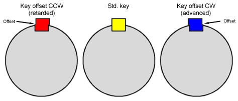
By a happy coincidence, the dimensions of the key are very similar to a key used in common automotive applications: the Chrysler “LA” (small block) V8 camshaft drive (and probably other brands and engines). Keys are available for this application with various degrees of offset, where the top is shifted slightly sideways from the bottom, causing a partial mis-alignment. These keys may be easily modified to fit the H-D installation. This is potentially useful in correcting production tolerances in components, including the right flywheel and pinion shaft, but also the pinion gears, cams, and breather assembly.
| |
|
Another purpose is to allow fine tuning of the cam(s) without re-grinding or using different cams. The offset will cause the entire cam gear train to be rotated forward or back (depending on which way the offset is installed) at the same point of flywheel rotation. This is not easy to do, as it requires disassembly of almost the entire engine, including splitting the flywheels, but no expense or modification to the cam(s) themselves.
Closing the intake valve sooner increases cylinder pressure and torque by trapping more compression, but loses some peak power; closing the intake valve later has the opposite effect. A change of 4° or more should be noticeable; less than this may not be of much use. More coarse adjustment may be made by “jumping” the cam gear 1 tooth forward or back on the pinion gear, and fine-tuning this effect with the key offset.
In 4 cam engines (45 & U-Series, etc.) the most important cam event (the intake valve closing point, as described above) may not match on the two intake cams (#2 & 3); either one, or both, may be “off”; the lobe centers may not be separated by the correct 315° interval. However, the key offset can be used to average the #2 and 3 to the same intake closing point, even if it’s not what the specification calls for. |
The thickness (width of the key & slot, in both the pinion shaft and right flywheel half) of both the H-D and Chrysler keys is identical at 3/16” (.188”). The length of the Chrysler key is greater at .730” compared to .460” for the H-D. However, the slots are longer than the key: .750” in the flywheel, and .650” in the pinion shaft. The total depth (height) of the Chrysler key is also greater at .300” compared to .173” for the H-D. The “top” (flat section, fits the flywheel slot) is about the same depth in both keys: .100”. The “bottom” (curved section, fits the pinion shaft slot) is much larger in the Chrysler key. However, the non-matching dimensions (length and bottom depth) can be trimmed with a grinder to fit. |
|
Harley-Davidson vs. Chrysler Key Dimensions | | Source | Part Nº | Thickness | Length | Total Depth | Shaft Depth | Flywheel Depth |
Harley-Davidson | 23985-12 | .188” | .460” | .173” | .073” | .100” |
| Chrysler | P4286500 | .188” | .730” | .300” | .200” | .100” |
|
|
The Chrysler key is available in offsets of 1°, 2°, 3°, 4° & 5° as a set, under the above part number. |
Chrysler Key: Degrees vs. Offset |
Key Color | Natural | Red | Blue | Gold | White |
Offset, Degrees | 1° | 2° | 3° | 4° | 5° |
Offset, Inches | .010” | .020” | .030” | .040” | .050” |
|
In calculating the amount of rotational change, do not use the Chrysler degree figures. The offset in inches will not change, but the Chrysler camshaft is larger in diameter than the H-D pinion shafts, so the same offset will have a greater effect in the H-D engine. The effect of a known amount of offset can be calculated based on the distance as a function of the circumference of a circle. The diameter of the circle is the diameter of the pinion shaft at the point of offset.
In a big twin, the smaller end of the taper is about .850”. The formula for circumference is 3.1416 (Pi) times the diameter. Therefore: .850” * 3.1416 = 2.67”, divided by 360° = .00742”, so each degree of rotation needs about .0074” of offset. |
Approximate Effect of Chrysler Offset in Big Twin Applications |
Key Color | Natural | Red | Blue | Gold | White |
Offset, Inches | .010” | .020” | .030” | .040” | .050” |
Offset, Degrees |
1.33° |
2.67° |
4° |
5.33° |
6.67° |
|
In a 45, the smaller end of the taper is about .750”. The same formulae apply: each degree of rotation needs about .00655” of offset. |
Approximate Effect of Chrysler Offset in 45 Applications |
Key Color | Natural | Red | Blue | Gold | White |
Offset, Inches | .010” | .020” | .030” | .040” | .050” |
Offset, Degrees |
1.5° |
3.0° |
4.5° |
6° |
7.5° |
|
Do not use the figures on these 2 tables directly; they have been provided for illustration only. For best results, you must measure the actual components yourself. Any dimensional changes will require new calculations.
Be careful not to remove metal from the sides (width) of the key, or the offset area (top). The most important revision is the depth: the new key must seat completely in both slots, or the pinion shaft will not be properly secured to the flywheel. Material must be removed only from the bottom (curved) part of the Chrysler key, as the top is already approximately correct. The length should be reduced by removing material evenly from both ends to retain the curvature. The bottom of the curve must be centered in the length. When properly modified, the key will seat completely up to the offset step in the pinion shaft slot. Remove the key - it should seat completely up to the offset step in the flywheel as well. Clean & dry all 3 parts thoroughly, and assemble. Lightly tap the pinion shaft with a block of wood, etc. to seat the taper. The shaft must not wiggle or click. If it rocks at all, the key is not fully seated, and more metal must be removed (probably from the bottom curved section).
The oil hole alignment between the pinion shaft and the right flywheel must be modified to allow full transfer of oil. I suggest the flywheel be modified, as the material is softer, and the shorter passage is easier to clean. Elongating the hole with a Dremel, die grinder, etc. in the direction of the offset by the same amount should be sufficient. Use Brake-Kleen etc. and then compressed air to be sure to get the debris completely out.
A trial assembly does not have to include the upper end parts, if your flywheel degree mark is accurate. The flywheels must be assembled & trued, cases should be closed, the cam chest assembled, tappets & blocks in place, etc. but the following steps should not be necessary:
» set flywheel end-play
» set cam end play
» install breather (unless relevant)
» install idler & generator gear
» install breaker
A complete rotation of the engine (720°, 2 full turns) should tell you whether the problem is fixed. A degree wheel on the sprocket shaft, and a dial indicator on the front intake tappet is the usual method. Be sure to rotate the engine forward only (counter-clockwise, as seen from the left side) to remove gear back-lash.
If the position is worse, you have the key offset facing the wrong way. If the position is improved, but not enough, use a key with more offset. If the position is now incorrect in the other direction, the offset is correctly positioned, but too large. Several trials may be necessary for best results. Be sure to make written notes on every change.
Select & install the final key and assemble the engine. Turn it over slowly by hand 2 full revolutions to check for piston to valve clearance (not required in side-valve engines). Remember that breather and breaker installations reference TDC and the flywheel timing mark, not pinion shaft position, so they will be accurate if installed “by the book”. However, the physical position of the rotor and breaker will change slightly to achieve this.
|
See these other Victory Library booklets |

| 
| 
| 
| 
| 
| 
| 
| 
|

| 
| 
|
|