|
|
 |
Here I will make various observations and comments on how the drum brakes function, and in some cases how to diagnose minor faults and make improvements. New material will be added regularly, and eventually better organized. Click below to jump directly to an individual topic. |
Single leading shoe components |
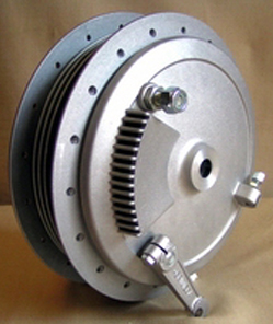
The “secondary” or “trailing” shoe (only present in single leading shoe systems, also called “1LS” or “SLS”) is applied against the direction of drum rotation by the rotation of the brake cam, which forces it away from the drum surface. The friction (and heat transfer, and effectiveness) is limited to the leverage and pressure of the cam. This system works equally well in either direction, and therefore prevents “roll-back”. “2-SLS”, or | |
|
twin single leading shoe, is a variant of this type using a hub with two drums back to back, and one mirror-image backing plate with conventional SLS shoes on either side. A Grimeca 180mm 2-SLS is shown here, right. Notice the single cam lever, and no linkage. Click the picture for a larger view. |
The “primary” or “leading” shoe (always present) is applied in the direction of drum rotation by the rotation of the brake cam, which “wedges” the leading edge of the shoe against the drum surface. The friction is the total of the wedging action, plus the leverage and pressure of the cam. In addition to increased pressure, this is also has a self-energizing “servo” effect in that the primary shoe is more tightly wedged in place by drum rotation without additional cam movement, so its effect increases automatically without any cam or hand-lever motion. The amount of torque contributed by a leading shoe is 27.9% higher than that of a trailing shoe, the proportionate effect of the primary vs. secondary shoe is roughly 56% vs. 44%. |
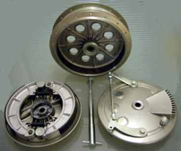
A dual leading shoe system (also called “2LS” or “DLS”, or “4LS” when two drums per wheel are used) substitutes another primary shoe and its cam &c. for the existing secondary shoe. This increases the braking force by about 14% (½ of the 27.9% higher effectiveness of the extra primary shoe since only one shoe is being changed). This makes for a lighter but more delicate control. A dual leading | |
|
shoe system only works in the designed direction, and is almost useless when reversed. Grimeca 230mm 4LS components are shown here, right. Notice the two cam levers, with connecting linkage. The 2nd backing plate is not shown, but would be a mirror image of the one in the right foreground, and visible through the drum holes. Click the picture for a larger view. |
Many SLS backing plates can be
converted to 2LS for a dramatic improvement in braking power with no weight penalty by some minor machine work. If the plate has a removable post to retain the “dead” (fixed) end of the shoes, this can frequently be replaced with another cam (inside the brake backing plate) and lever (outside the plate), the existing secondary shoe is either replaced by another primary shoe reversed (preferred: the material and thickness may be different), or simply reversed, and external linkage added. Some brake cams can work as-is, some must be modified, and some can be adapted from another type. This has been done successfully by the Triumph & BSA factories to the 1967 SLS drums, and by aftermarket manufacturers to the H-D 1936-57 spring fork drum and 1964-72 Sportster full-width drum. |
General comments
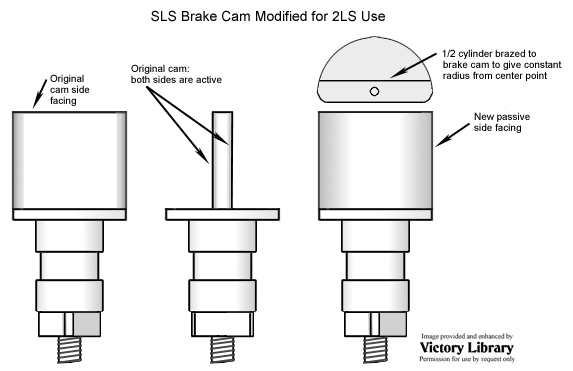
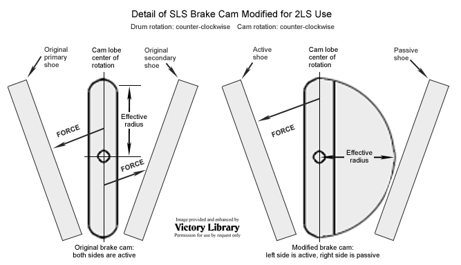
The original single leading shoe cams are laterally symmetrical, and move the active ends of both the primary (leading) and secondary (trailing) shoe simultaneously. This is the wrong shape for a 2LS cam, which must move only the active end of a single primary shoe (correct profile: one side is curved, one side is flat). The leading edge of each shoe must be chamfered to allow ”wedging” action without grabbing. |
The cam shape can be left flat as original on the active side, and modified to curved on the passive side, although the location of the radius is critical. Harley-Davidson SLS components are used here for illustration but the principle
is the same, click each for a larger view.
| |
|
As an alternate, a post can be added to each side of the backing plate next to each cam to support and locate the passive end of each shoe. A possible method is to shorten each shoe from the “back” (secondary, non-cammed end) by slightly more than the cam eccentric distance (½”?) and locate it on a very strong new post (which must be inserted and welded into the backing plate). Now the existing cam will lever the primary end of each shoe correctly, and pass by the secondary (non-cammed) end harmlessly, so the existing cam contour will work without modification (only one side is shown, duplicate in mirror for the bottom).
Since the new post will be taking a lot of force, it must be absolutely rigid. One proven method of assisting it is to make a tie-bar that connects both posts across the top of the shoes on a diagonal. It can be a beam or as simple as a piece of 1/16” flat plate with a hole in the middle for the axle/sleeve. Since it’s in compression, the cross-sectional area should be high - a tube or I/H shape is preferred over a strap.
Reverse one shoe, since the leading edge must be next to the extra cam. Even though the same lining material is used on the primary & secondary shoes, a good installation is not only arc-ground to the drum ID, but the primary shoe is “cut back” on its leading edge a bit to prevent “grabbing”.
From Vintage Brake: “First mount the relined shoes on the backing plate. Place .015” shims between the pivot cam(s) and shoes, and turn on the lathe (300-350 rpm) to .010” under drum I.D. in .010” cuts. Lay back leading edge of leading shoes in ½ increments to minimize initial “bite” if brake is too “grabby”, especially when hot. |
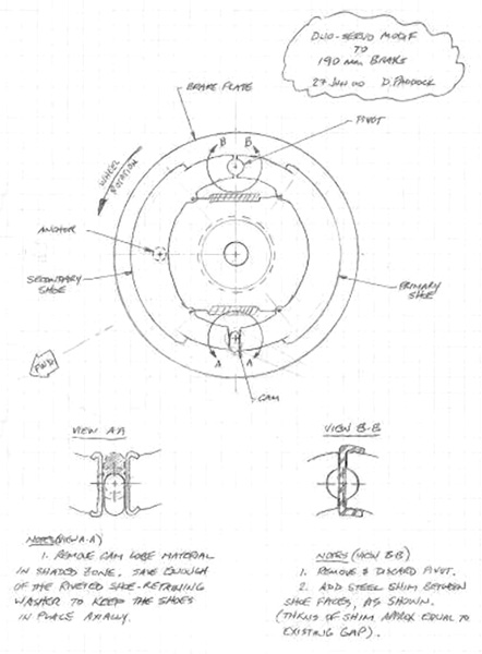
BritBike Forum member ca7a (other Board members: contact him through the Board) has successfully converted a BSA Gold Star 190mm brake to 2TL. He comments: |
“My TLS mod is based on the Bendix Duo-Servo self-energizing concept which has been used on almost all automotive drum brakes after they went hydraulic in the late thirties. Marks’ Mechanical Engineers Handbook has a good explanation of this design concept (click the drawing for a larger view). | |
|
Re my 190 mm brake mod, I have some detail photos but they’re not too revealing of the overall view. I attached a sketch which shows the modification much better. In addition to its superior stopping capability, this mod is simple to construct and presents a stock exterior to the observer. The duo-servo concept provides the same braking effect forwards and backwards, a feature that can’t be had with the two-cam TLS.
Keep in mind this is a work-in-progress; it’s by no means ready for adaptation. There is still work to be done re the linings viz., arc length, chamfer and coefficient of friction. Roy Bacon noted in his ‘BSA Twins and Triples’ book that BSA’s 1962 fully floating front brake ‘worked well enough to require the leading edges [of the linings] to be taken back 1-1/4 inches to prevent them from biting too fiercely.’ My mod has a similar caveat, so proceed carefully!”
D/ |
|