|
|
 |
The concept that maximum power is obtained by zero pressure in the exhaust is only partially true. There should be absolutely no back-pressure from the collector rearward, but the diameter of the system beginning with the exhaust valve is a compromise. The highest efficiency for the system requires a minimum speed for good exhaust gas velocity to insure that gas does not “back up” into the chamber during overlap at low engine speeds, and that the “suction” (negative pressure pulse) effect of a resonant (tuned length) and/or collector (overlapping exhaust pulses) system is optimized.
To predict what primary size will be best for a specific motor, you must know where you want the engine to develop peak torque. If the existing torque peak is at bit lower RPM than you prefer (typical in under-cammed or stock motors), it can be “bumped” a bit by increasing the primary diameter. If the torque peak is too high (motor is “peaky”, with no range and poor recovery from gear changes), the peak can be adjusted down by using a smaller pipe. A change of 1/8” in the primary diameter will raise or lower the peak torque RPM by 500 or so. |
This factor slightly overlaps the effect of primary pipe length, but the pipe length generally will not change the peak torque or the RPM at which it occurs. A length change has the effect of improving the torque on only 1 side of the peak by “borrowing” it from the other side. A shorter pipe improves the torque after the peak (reduces it at lower RPM), preventing the curve from flattening out so quickly as speed increases. A longer pipe extends the torque curve backwards to improve the engine's flexibility, at the expense of after-peak torque. Less stall speed is required, and the motor will pull taller gears; this re-tunes a 4-speed motor for better operation with Torqueflite, etc. |
For best effect, the gas speed in the primary tube at the peak torque RPM should be about 240 feet per second. The formula to calculate pipe size is: |
Area of Primary Pipe = RPM × Cylinder Size ÷ 88,200 |
This determines the pipe's cross-sectional area, from which we can calculate the ID. Typical exhaust pipes are 18ga. (wall thickness of .049”), so the OD will be .098” larger. From this we can construct a formula for an 8 cylinder motor, and factor in the 18ga. wall thickness: |
Area of Primary Pipe = RPM × Motor Size ÷ 705,600 |
Pipe ID2 = RPM × Motor Size ÷ 705,600 ÷ .7854 |
Pipe ID2 = RPM × Motor Size ÷ 554,177 |
ID = (RPM × Motor Size ÷ 554,177).5 |
OD = (RPM × Motor Size ÷ 554,177).5 + .098” |
The following Chart shows exhaust pipe outside diameter, based on this formula, for various motor sizes and speeds. To determine if your pipe size is large enough, search across the top row for your motor size (interpolate if in between 2 sizes), and then down that column for your current pipe OD. If the peak torque RPM in the left column is high enough, your pipe is not a restriction. If the peak torque RPM is lower than where you feel your torque peak is, look for the pipe OD on the line with your torque RPM.
If your primary pipe's wall thickness is 16ga. (.059”), add .020” to the OD figure to compensate. |
LA Motors: Pipe Size @ Peak Torque RPM vs. Motor Size |
Motor Size |
273” |
318” |
340” |
360” |
392” |
410” |
RPM | Primary Pipe Outside Diameter, Inches |
3000 |
1.31 |
1.41 |
1.45 |
1.49 |
1.55 |
1.59 |
3250 |
1.36 |
1.46 |
1.51 |
1.55 |
1.61 |
1.65 |
3500 |
1.41 |
1.52 |
1.56 |
1.61 |
1.67 |
1.71 |
3750 |
1.46 |
1.56 |
1.61 |
1.66 |
1.73 |
1.76 |
4000 |
1.50 |
1.61 |
1.66 |
1.71 |
1.78 |
1.82 |
4250 |
1.54 |
1.66 |
1.71 |
1.76 |
1.83 |
1.87 |
4500 |
1.59 |
1.70 |
1.76 |
1.81 |
1.88 |
1.92 |
4750 |
1.63 |
1.75 |
1.81 |
1.85 |
1.93 |
1.97 |
5000 |
1.67 |
1.79 |
1.85 |
1.90 |
1.98 |
2.02 |
5250 |
1.71 |
1.83 |
1.89 |
1.94 |
2.03 |
2.07 |
5500 |
1.74 |
1.87 |
1.93 |
1.99 |
2.07 |
2.12 |
5750 |
1.78 |
1.91 |
1.98 |
2.03 |
2.11 |
2.16 |
6000 |
1.82 |
1.95 |
2.02 |
2.07 |
2.16 |
2.20 |
Note: 392” is 340/360 block stroked with 3.79” crank; 410” is 340/360 block stroked with 4.00” crank |
B/RB Motors: Pipe Size @ Peak Torque RPM vs. Motor Size |
Motor Size |
383” |
400” |
426” |
440” |
451” |
494” |
RPM | Primary Pipe Outside Diameter, Inches |
3000 |
1.54 |
1.57 |
1.62 |
1.64 |
1.66 |
1.73 |
3250 |
1.60 |
1.63 |
1.68 |
1.70 |
1.72 |
1.80 |
3500 |
1.65 |
1.69 |
1.74 |
1.77 |
1.79 |
1.86 |
3750 |
1.71 |
1.74 |
1.80 |
1.82 |
1.84 |
1.93 |
4000 |
1.76 |
1.80 |
1.85 |
1.88 |
1.90 |
1.99 |
4250 |
1.81 |
1.85 |
1.91 |
1.93 |
1.96 |
2.04 |
4500 |
1.86 |
1.90 |
1.96 |
1.99 |
2.01 |
2.10 |
4750 |
1.91 |
1.95 |
2.01 |
2.04 |
2.06 |
2.16 |
5000 |
1.96 |
2.00 |
2.06 |
2.09 |
2.12 |
2.21 |
5250 |
2.00 |
2.04 |
2.11 |
2.14 |
2.17 |
2.26 |
5500 |
2.05 |
2.09 |
2.15 |
2.19 |
2.21 |
2.31 |
5750 |
2.09 |
2.14 |
2.20 |
2.23 |
2.26 |
2.36 |
6000 |
2.13 |
2.18 |
2.25 |
2.28 |
2.31 |
2.41 |
Note: 451” is 400 block stroked with 440 crank; 494” is 400/440 block stroker with 4.15” crank |
Remember that your peak torque RPM will always be lower than your peak HP RPM. The separation between peak torque and peak power is roughly proportionate to your range of useable power (wider is better). Be realistic in your estimates and plans - peak torque @ 7000 RPM sounds good, but is almost certainly beyond the breathing ability of even a professionally-built race motor, and if true will make the car impossible to launch. Note that 1-1/2” pipe is large enough for a 273” motor with max torque @ 4000 RPM. A 360” only needs 1-3/4” for 4200 RPM. A 440” is fine @ 4500 RPM with 2” primaries.
If choosing pipes for a 4WD, van, towing, etc. keep the size small to improve torque where you need it most - the lower RPM ranges, typically 2500-3500. | One exception where use of a larger pipe (than indicated by the above formula) will help power is, of course, motors using nitrous oxide, supercharger or turbocharger. In these cases, size the pipe for the expected peak torque, not the motor size. | Another instance where a slightly larger pipe may help is where the departure angle of the pipe from the flange is very sharp (typically downward). The added cross-sectional area immediately after the flange apparently helps reduce the restrictive effect of a small radius after the port. This partially explains why some header models or brands work better than others with similar dimensions. |
Minor Improvements |
If possible, slightly enlarge the inside of the flange opening in the header itself to produce a sharp step (be careful of grinding off the tube weld). Do not radius the edge. A 1/16” bevel is generally possible and will help. If there is not much room, don't grind all the way into the flange - a 45° angle is fine. This has a minor anti-reversion effect, helping to prevent back-flow at low engine speeds; helps clean up idle quality, etc. |
If the primary pipe inside diameter is more than 1/8” larger than the actual port opening in the head, the header flange bolt pattern can be slotted slightly to raise the centerline of the primary pipe above the center of the port, until the bottom of the pipe just matches. This puts the pipe's effective center closer to the most active area of gas flow, and the mis-alignment at the roof allows the highest-pressure gas an easier path away from the port; also adds some degree of anti-reversion.
If controlling reversion is more important than maximum port flow (e.g. primary diameter is very large), Vizard suggests the mis-match should be at the bottom of the port where gas flow is slowest, and therefore most likely to reverse-flow at low engine speed. |
An easy way to effect a small increase in exhaust efficiency, if space permits, is to move the header out away from the port by 1/2” or more (using an extra gasket and longer studs or bolts). This moves the restrictive angle farther away from the port - every little bit helps here. It also reduces local exhaust port temperature in the head slightly. An easy spacer is an extra header flange or 2, but be sure that the transition from the extra flange to the header is not restricted. The extra flange may be slightly larger than the port opening in the head, but must not step down entering the header. Do not taper, blend, or bevel the extra flange to act as a transition between the port and the header. |
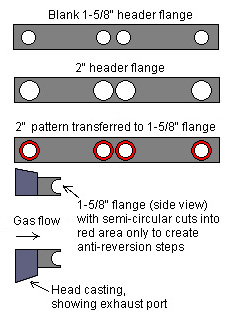
Anti-Reversion Plate |
If the header in use is substantially larger than other available choices for the same motor (i.e., you're using 2” OD, but headers are also available in 1-5/8”, etc.), an inexpensive anti-reversion plate can be made from a bare flange with the smaller size (1-5/8”). Do these steps in order:
» Match the extra flange openings to the exhaust ports.
» Lay it over your actual 2” header flange.
» Spray paint, mark etc. the 2” openings around the 1-5/8”
openings (they will be concentric circles).
» Remove the marked area as shown, using ball end
carbide cutter, etc.
I would suggest the following rules for best effect:
» The extra, smaller flange be no smaller than your motor's
exhaust port.
» The extra flange be at least 1/4” smaller than the header
in use (if using a header with 2” primaries, the extra flange
should be 1-3/4” maximum). |
|
|
» Make sure there's enough room to move both sides of the header away from the motor by 3/8”
or so (the header flange thickness).
» You may need an extra gasket between the flanges, or sealer may do (Vizard uses silicone here)
» Longer bolts or studs will probably be needed; remember to use sealant on B/RB motors due to
water in the headbolt holes.
|
|