|
|
 |
Toyota A340E Automatic Transmission
Performance Modifications
by Jeffrey Diamond
Last revision: August 1, 2017 |
Here I will make various observations and comments on how the A340E transmission functions, and in some cases how to make improvements. New material will be added regularly, and eventually better organized. Click below to jump directly to an individual topic. |
Identification
The A340E is not a specific, limited purpose single transmission, but a class or series of closely related products constructed from identical or very similar components, but not completely interchangable. There are different input and output shaft types, different bellhousing bolt patterns, different sump capacities, provisions for a front wheel drive transfer case, different valve bodies, and other major variants. |
Toyota letter codes
The Toyota alpha-numeric transmission designator codes mean: |
A | Manufactured by Aisin-Warner |
3 | 3rd generation (1986-2007) |
4 | Number of forward internal gear ratios |
0 | Toyota series number |
E | Electronic control |
Applications
There are (at least) three different bellhousings for the 2JZ engine, based in part on which torque converter will be used: normally aspirated GE (Aristo, Chaser, Lexus SC300, GS300, Soarer, Supra NA, &c.), 1JZ-GTE (Soarer TT), or GTE (Aristo and Supra TT).
The basic main TT transmission case will accept bellhousings specific to other engines which have been manufactured with another variant of the A340E during its 3rd generation life span 1986-2013. This suggests that the TT main transmission case, and at least some of its internal parts, may be adaptable as an upgrade to other engines.
This includes Lexus and Toyota cars and trucks produced for both the Japanese home market and export, and also some Jeep, Isuzu, and Volvo vehicles; see the Wikipedia article:  . .
Other A340E variants
The automatic transmission used with the earlier 1JZ-GTE turbocharged engine is somewhat different (and less robust), with a smaller diameter torque converter and “J1” bellhousing casting. Appplications include the Toyota:
» Chaser (JZX81)
» Cresta (JZX90)
» Crown Athlete V (VJZS170)
» Mark II (JZX100)
» Mark II Blit (JZX110W)
» Soarer GT (JZZ30)
» Supra MK III (JZA70, Japan and Australia only)
» Tourer (JZX110)
» Verossa (JZX100)
The Lexus SC300 has a J1 on the bell housing, and it is deeper than the J2 (GS300) and J3 (TT only). The main transmission case may have a 3F570 sticker. The SC300 uses a slip yoke on the output instead of the 3 spoke flange which is why the write-ups for the swap into the SC requires drive shaft mods. Using the GS300 flange on the Aristo transmission allows it to bolt to the stock GS300 drive shaft.
The 2JZ-GE installed in the GS300 uses the J2 bellhousing. All three bellhousings attach to any JZ engine, and probably to many other A340E main transmission cases, but this does not guarantee the compatibility of the internal parts.
The usual rule for bellhousings (individually, or assembled to the transmission) is that the cast-in letter identifies the engine series bolt pattern at the forward end of the bellhousing, and the main transmission case type matches the rear bolt pattern of the bellhousing. “U”: 4.0 &c. V8; “VZ”, “MZ”, “GR”: V6. If there is more than one bellhousing for an engine series, a number will follow the letter.
In addition to the bolt pattern differences, the three bellhousings are different lengths (depths from face to face), and require different length input shafts. This prevents a 3F310 main transmission case from adapting directly to a UZ V8 engine using the “U” bellhousing: it's too short, with the wrong spline pattern on both the input shaft and the torque converter. The J1 depth has been measured as 122mm (4.803”). |
Transmission ratios
The internal transmission ratios are “staged” and progressive, with the widest ratio split (and the lowest RPM recovery) between 1st and 2nd, less between 2nd and 3rd, and least between 3rd and 4th (overdrive), as shown in the following Table. This is consistent with good engineering practice.
A340E internal transmission ratios |
Gear ratios |
RPM % recovered by shift |
RPM % lost by shift |
RPM after shift |
1st |
2.804:1 |
|
Shift out of 1st at 5,000 |
Shift out of 1st at 6,000 |
Shift out of 1st at 7,000 |
2nd |
1.531:1 |
54.6% |
- 45.4% |
into 2nd at 2,730 |
into 2nd at 3,266 |
into 2nd at 3,525 |
3rd |
1.000:1 |
65.3% |
- 34.7% |
into 3rd at 3,276 |
into 3rd at 3,919 |
into 3rd at 4,330 |
4th |
.705:1 | 70.5% |
- 29.5% |
into 4th at 3,822 |
into 4th at 4,572 |
into 4th at 4,935 |
“Evenly split” (rather than progressive) ratios sounds intuitively correct but in fact doesn’t work. The higher air resistance and lower mechanical advantage at higher MPH require constraining the engine more tightly in its peak power range. The standard A340E’s ratio progression (as shown in Column 3 of the above Table) produces superior results in quarter mile acceleration and top speed to a theoretical transmission with the same 1st and 4th gears (2.804:1 and .705:1) but with equal ratio splits: 2.804:1, 1.770:1, 1.172:1 and .705:1 ratios are each reduced by about 37% for the next higher ratio.
As the vehicle’s top speed increases (such as in the Supra), better RPM recovery becomes crucial. If the differential ratio is tall enough, the vehicle will not be able to reach high gear at all - it will be faster in the next lower (numerical) gear.
As the test speed or distance shrinks (from 1/4 mile, to 1/8 mile, to 0-60 mph, to 60 ft.) traction, overall gear ratio (1st gear × axle), stall speed, and chassis movement become more important than power. In a 1/2 mile race these have minimal value. At Bonneville, even weight has almost no effect, very fast cars carry tons of ballast.
For a comparison with American 4-speed automatic overdrive transmissions, see my article here:  . .
Having only 4 forward gears limits the application somewhat. When designing the internal ratios, the 1st gear ratio should be high enough to move the vehicle with whatever differential ratio it has; a common test is to multiply the 1st gear and axle ratios, with 10 being a safe result. Less than 10 (e.g., 2.50 1st gear × 3.00 axle = 7.50) yields reduced low speed performance, and much more than 10 (e.g., 3.00 1st gear × 4.00 axle = 12.00) requires a wider (less efficient) split among the intermediate ratios. By comparison (the later A350E is an example), a 5-speed transmission could have a “stronger” (higher numerically) 1st gear, closer ratio splits, and still have the same overdrive final gear - all it takes is money and weight.
I’ve written an Excel (.xls) worksheet that analyzes the A340E ratios with most common Toyota and Lexus differential ratios, common tire and rim sizes, and calculates MPH per 1,000 RPM, RPM changes with each shift, MPH with selected RPM, &c. E-mail me for a free copy:  . .
Overdrive function
This transmission, like all modern transmissions, has an overdrive (indirect) final gear, in which the output shaft, driveshaft, and differential pinion gear turn faster than the crankshaft, which reduces engine speed in 4th gear for reduced wear, noise &c. and increased gas mileage and top speed.
It is important to understand that only the engine and transmission speeds are reduced in overdrive. The driveshaft speed still tracks the differential ratio with regard to RPM, and may reach a dangerous level of vibration or imbalance at high vehicle speed.
Column 3 in the Table below gives the overall 1st gear ratio for common Toyota and Lexus differentials using the A340E 1st gear. |
Toyota and Lexus RWD differential ratios (200mm ring gear) |
Axle ratio (ring gear ÷ pinion gear) |
Effective axle ratio in overdrive |
Overall 1st gear ratio |
3.133:1 |
2.209:1 |
8.785:1 |
3.266:1 |
2.303:1 |
9.158:1 |
3.538:1 |
2.494:1 |
9.921:1 |
3.769:1 |
2.657:1 |
10.568:1 |
4.083:1 |
2.879:1 |
11.449:1 |
4.272:1 |
3.012:1 |
11.979:1 |
Torque converter
All modern automatic transmissions have torque converters, and all torque converters have a “stall” characteristic (the maximum engine speed before the engine stalls or the car moves). There is no such thing as a “stall converter”.
Stall speed with the same torque converter will vary roughly with the square root of the engine’s torque output (in ft./lbs.) at the stall speed (sounds like circular logic, doesn’t it?). The industry has created a rating factor for comparing torque converters, the “K” factor: RPM = K × (T.5). Some manufacturers supply this data; if attempting to approximate it remember that the relevant torque output is not necessarily peak torque (although with a very high stall speed it will be close), but the torque at the (probably lower) actual stall speed. Sonnax (a well-known manufacturer of high-performance automatic transmission parts) suggest that a better choice for track use is a stall speed between 500 and 700 RPM below the engine’s torque peak.
If you use a converter designed for a larger engine your stall speed will be lower than the manufacturer’s description. E.g., if the manufacturer identifies your Turbo-Hydramatic 400 converter as “3,500 RPM stall speed”, this was almost certainly with regard to its characteristics with a Chevrolet V8 engine developing perhaps 400 ft./lbs. of torque at that speed (which places the K factor value at 175). When installed behind a 2JZ-GTE engine with about 50% less displacement but developing perhaps 300 ft./lbs. of torque under boost at that speed, the actual stall speed will be closer to 3,000 RPM.
Engines built for increased power with radical cams suffer from reduced low speed power, and a converter with increased stall speed allows the engine to spin faster for a better launch. The increase can be done by either changing the angle, diameter or pattern of the fins, modifying the clearance between internal components, reducing the diameter of the shell (outer body), or any combination of these.
There is a practical limit to this - if you have too much power or too much stall speed, you simply spin the tires.
Converters prepared for serious use (turbocharger, supercharger, nitrous) frequently have their fins, which are commonly crimped to the torus (outer) shell, brazed in place to prevent them from “laying over” (bending) from hydraulic pressure under severe load - expect to spend money on this.
In addition to the 1st gear torque multiplication, the torque converter also multiplies engine torque by perhaps a factor of 1.9:1 for the first few feet of roll-out until the stator spins up to speed. With the A340E 1st gear it gives a brief but effective overall 1st gear ratio of about 5.3:1.
Converter choice symptoms
Stall speed is too low when:
» the engine dies easily when put in gear, or on slight acceleration from a stop
» the idle speed drops more than a few hundred RPM when put in gear
» the idle in gear is rough
» the launch is poor
» the throttle feels “dead”
» there’s no power at low speed with a hot cam
» there’s no boost at low speed (with your intended turbine A/R)
Stall speed is too high when:
» the engine speed hardly drops when put in gear (or not at all)
» the engine will buzz with throttle motion in gear, but the car won’t move much
» the gas mileage is bad at cruising speed, and worse around town
» the transmission fluid temperature is high
The best stall speed is when:
» the engine speed drops significantly when put in gear, but the idle is stable
» the engine will buzz quickly with throttle motion
» the launch is much better
» the low speed power is much improved
» boost is present before or at launch (with your intended turbine A/R)
» the gas mileage is only slightly down at cruising speed (but may be worse around town).
Locking converter
The transmission also has a locking clutch pack inside the torque converter to further reduce engine speed under light throttle cruising conditions. This engages automatically when these conditions are present:
» Pre-set minimum vehicle speed has been reached
» Engine vacuum is above a pre-set level
» Throttle position is less than 30% open
This eliminates all torque converter slippage and stall speed, which reduces transmission fluid temperature. The TCM automatically disengages this feature when the throttle opening exceeds 30%, because the clutch pack has limited torque capacity.
|
High performance transmission |
Of particular interest is the special transmission installed in the 1993-2003 Toyota Supra RZ Mk. IV (JZA80), and Toyota Aristo 1991-1996 V 3.0 (JZS147) & 1997-2005 VVT-i V300 (JZS161) with 2JZ-GTE twin turbocharged engines, as well as supplied with Aristo engines by the JDM importers. For brevity, “TT” will refer only to this transmission, and “NA” will refer to all other A340E transmissions including 2JZ-GE regardless of application.
There is also some confusion, and difference of opinion, as to the exact meaning of “A341E”, both among builders and tuners, and in the actual Toyota service literature. In some it refers specifically to the special TT transmission, in others it refers to the A340E variant installed in the LS400 (but not the SC400) UZ V8, which has a different mainshaft length, different bellhousing (identified with the letter “U”), and 2.531:1 (taller) 1st gear ratio. Click here for more details:  . . |
Visual identification |
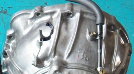
The TT model’s larger bellhousing* can be identified by the large characters “J3” cast into the upper surface (and therefore not visible in the car) as shown. The 1991-1996 pre-VVT-i main transmission case also has (had) a large sticker identifying the actual Toyota part number 35010-3F310. The 1997-2005 VVT-i main transmission case sticker is 35010-3F320. Click a picture for a larger view on a separate page. |
|
 |
|
 |
|
 |
The main transmission case (behind the bell housing) is also identified by a smaller cast-in 2-digit number found on a raised rib on the upper surface (and therefore not visible in the car) toward the tailshaft. These numbers include 15, 17, 18, 21, 23, 25, 26, 32, and 37. My suspicion is that these are not simply a list beginning with 1 (1, 2, 3, 4, &c.) but some dimension in millimeters locating the separate transmission mount (which bolts to the chassis) to the transmission case. Click the picture (showing casting 37) for a larger view on a separate page. This means that an exchange rebuild may not install with the original transmission mount. Please add to this list if you can clearly see the number, and most especially: if you know what engine and chassis it’s from, e-mail me  . . |
|
 |
Correcting alignment |
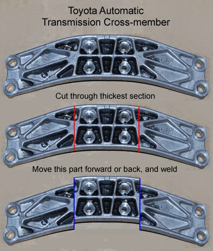
My Lexus SC300’s killer TT transmission didn’t line up with my transmission mount, the professionals at Empire Performance in Deer Park, Long Island, New York analyzed, dissected, re-aligned, and welded a different Toyota mount to suit my new transmission case, as shown in the picture, click to see a larger view on a separate page. Click here for their web site:  . . |
|
 |
Unique TT features |
» The Aristo TT transmission has a 3-bolt flanged output (as shown) with driveshaft to match. The Supra’s output (not shown) is a male
splined shaft with a female splined yoke on its driveshaft.
» The output spline has 23 spline, 1.020” OD, different from the NA transmission with 21 spline, 1.100”.
» The transmission is longer overall (takes a shorter driveshaft).
» It has 5 solenoids, numbers 1-4 activate linearly allowing more precise transmission control.
» The 5th solenoid (rather than the NA’s throttle cable) controls line (internal hydraulic) pressure electronically for smoother shift modulation.
The NA’s throttle cable is absent.
» It has a larger fluid sump (this may be the same as the IS300 2JZ-GE sump). |
 |
» The Toyota TCM retards spark timing during a shift to reduce power without losing turbine spool.
» The Toyota TRAC TCM closes the TRAC throttle butterfly during a shift to reduce boost.
» It has one extra clutch pack.
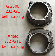
» * Larger bellhousing; click on the center right image for a larger view on a separate page.
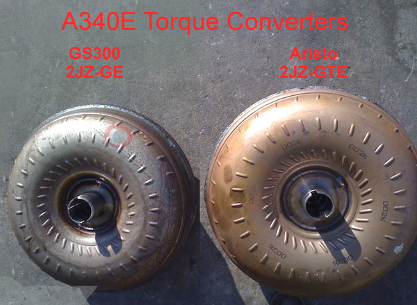
» Larger diameter 2,600 RPM stall speed converter. Click on the lower, right image for a larger view on a separate page.
» The TT converter attaches to the TT-only flex plate with 17mm head, 10mm × 1.25mm thread bolts, vs. the NA which uses 14mm head,
9mm × 1.25mm thread bolts. The TT bolt circle is also larger in diameter. |
|
Swapping the Aristo TT transmission into a Lexus GS300
An extremely detailed and useful article on this popular swap can be found on the “Club Lexus” site, click the link:  . . |
Transmission fluid
The TT transmission should use only genuine Toyota Type T-IV transmission fluid (Toyota part # 00279-000T4). A Toyota transmission engineer states: “The reason the TT... uses T-IV is because those transmissions have flex lockup and “intelligence” control. The TCM monitors input and output shaft timing to maintain constant shift speed over its life. The TCM’s control calibration is matched to the T-IV’s fluid’s friction coefficient and temperature characteristics. Any Toyota transmission with flex lockup (duty cycles linear solenoid at low speed and load) uses that fluid. Otherwise Dexron III is used. The clutches and seals are the same. Using Dexron in a T-IV transmission could cause shift flare, shock or lockup shudder. The Toyota stuff is very high quality (mineral based).” |
A340E TT torque capacity limits
The TT A340E works well enough with the stock 2JZ-GTE twin turbochargers but needs some modification when the turbocharger boost level is elevated, even with the original (small) turbochargers. These changes include: |
» Modified valve body calibration to improve shift quality. This is available as an expensive service, using your valve body or as an
exchange, from several Supra specialists. TransGo offers a relatively inexpensive “Reprogramming Kit”, click the picture for
details. It can be installed without removing the transmission from the car. It’s available from Summit, Jeg’s, &c.
» Additional friction clutches (and matching steel plates) can be added to some clutch packs for more surface area.
» The 4th (overdrive) gear clutch pack is insufficient for drag racing, and overdrive must be switched off during any WOT runs.
The differential ratio and rear tire size must be selected to allow the entire pass to be completed in 3rd (direct) gear. When
selecting or de-selecting overdrive, let off the throttle long enough for manifold boost pressure to drop off.
» The converter’s locking clutch is especially fragile, and will quickly fail if boost is applied when locked. The factory TCM should
prevent this by cancelling lock-up at more than 30% throttle, but not as reliably as we would like.
» Internal fluid passages ported and enlarged for better cooling and faster application of fluid pressure.
» Pressure regulator boost valve modified for response time.
» Generally, the line pressure is raised to apply more force to the clutches. |
 |
Extremely high power levels, above perhaps 500 hp, will fail some mechanical (as well as friction) components, specifically the 2nd gear sprag. There are at least two very expensive replacements available, which should be professionally installed. Some rebuilders will only accept 1991-1996 3F310 (non-VVT-i) cores.
Let me offer a warning to those considering uprating their A340E TT transmissions (such as to the ATF Stage II): the revisions are not buffet-style in which you can select exactly which new, better, extra parts to use. It’s a package, and based on my early results:
1. The shifts are all extremely hard (BANG) regardless of throttle opening, which means wet weather driving is extremely dangerous, backing off does nothing. The car will loop at 10 mph on the 1-2 shift if the wheels are turned.
2. My Aristo TCM still retards the spark on shift, but the reduced power (down from 520 hp) is still huge, so the tires smoke on the 1-2 shift, and the car will change lanes if the wheels are not straight.
3. My TT automatic shift points are stock, and probably earlier than best for power, but the acceleration is so fast in 1st & 2nd that I can’t rely on watching the tach and moving the shifter consistently. If you want to adjust your automatic shift points you may need 3rd party software.
4. Any manual transmission offers far better traction control during a hard run (just lift when the clutch is depressed), but you lose boost and have to spool up again in the next gear. Power shifting (throttle is fully open with the clutch depressed) fixes this but may break the transmission, and only the rev limiter will save the engine if you screw up.
Temperature Control
The primary cause of automatic transmission failure is excessive fluid temperature. The original fluid cooler is housed in the lower section of the engine’s radiator, and is adequate for street duty with the stock engine.
For sustained boost, more transmission cooling capacity is necessary. This is usually done by adding a remote transmission fluid cooler, either replacing or after and in series with the radiator’s cooler. This allows the radiator’s water temperature to partially regulate the transmission fluid temperature. When shopping, the only difference between an engine oil cooler and a transmission fluid cooler is frequently that the engine oil cooler has larger fittings (1/2”-14 NPT, &c.); if you get a good price just adapt them down as needed (3/8”-18 NPT, &c.).
Slowing the engine down (use overdrive where practical), and locking the converter (light throttle only) help reduce fluid temperature.
If using a temperature gauge, the most useful information is the temperature of the fluid in the transmission pan closest to the pump pick-up: what the transmission will use next. If you can’t tap into the pan, the transmission’s 10mm “out” line (to the cooler) is the next best place.
If the gauge shows above 200° F, stay off the throttle. Like engine oil temperature, transmission fluid temperature tracks load and it will rise during a run. If it doesn’t recover to an acceptable temperature quickly you need a bigger cooler, a second cooler, or a cooler with a fan. In general, there is no danger of over-cooling the fluid, but if you drive in really cold temperatures, a Tru-Cool bypass is available that short-circuits the cooler when the fluid is below 175° F. |
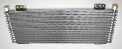
My Lexus SC300 with Aristo 2JZ-GTE uses a water-only Mishimoto radiator, plus the 22” wide × 8½” tall Tru-Cool 45,000 BTU transmission fluid cooler #47391, with 3/8” fittings; click the image for a larger view on a separate page.
A cooler is actually not a “radiator” which cools by radiation from which heat is given off by all surfaces (even when motionless
in a vacuum). Instead, it cools by convection: an air current is heated by passing through the core. Air motion is critical; air only
flows in one direction: from high pressure to low pressure. If both sides of the cooler core are open to atmospheric pressure, it
becomes a radiator - and far less effective. If it’s masked from the engine fan’s draft, it needs a duct or its own fan. |
 |
Cooler design affects its efficiency, more specifically its ability to reduce temperature per square inch of core surface.
The most important cooler dimension is its core area (height and width), not its core thickness; use the largest area you can fit or afford. Increase core thickness if the available area is small (but it can’t hurt if you have the room).
“Stacked plate” construction has the highest heat rejection per square inch of core area, as well as the lowest pressure drop through the core, and the fluid remains in the core longest. Somewhat lower in efficiency is “plate and fin”, last is “tube and fin”. If space is limited, high efficiency is a priority.
Automatic transmission fluid life expectancy can be as long as 100,000 miles at an operating temperature of 175° F. Above this point, the rate of oxidation doubles with each 20° F increase in fluid temperature. The chart below illustrates the relationship.
Transmission fluid temperature vs. life expectancy |
Temperature Miles |
Temperature Miles |
Temperature Miles |
Temperature Miles |
Temperature Miles |
Temperature Miles |
Temperature Miles |
Temperature Miles |
175° F = 100,000 |
195° F = 50,000 |
215° F = 25,000 |
235° F = 12,500 |
255° F = 6,250 |
275° F = 3,125 |
295° F = 1,562 |
315° F = 781 |
Cooler installation
Before the transmission actually fails, the worn-off clutch friction material comes loose and flows through the fluid distribution circuit, which contaminates the pick-up filter, pump, valve body, and converter. Plumb a good hydraulic cartridge filter in the line leading from the transmission to the cooler. This prevents debris from becoming trapped in the cooler core. Note: the cartridge base will only flow in the correct direction (probably “in” from the side and “out” from the center). If you accidently reverse the lines, the fluid will not circulate at all and the transmission will overheat. To detect this:
1. The cooler core will be cold to the touch after 10 minutes of light throttle cruising (instead of significantly hotter), and
2. A fluid temperature gauge will show ambient air temperature, indicating that no warm transmission fluid has reached the gauge sender.
I prefer hard steel lines to & from the cooler and filter wherever practical, with the shortest possible length of flexible hose to permit service and allow for component movement. Break the longest straight steel line with compression fittings so you don’t need to snake that curve out from the suspension.
Use the largest diameter line that makes a practical radius where turns are needed, even 3/8” is 9% smaller than the factory 10mm (.394”) line.
I drill the ID of all brass (mild steel corrodes, stainless is too expensive) fittings (reduction bushings, “T”s, pipe to hose, &c.) slightly oversize, and countersink & radius any changes in diameter to improve flow. Never use a 90° fitting if there is an alternative.
Braided stainless lines have only a single useful purpose here: as armor if something in the driveline fails (converter, damper, pulley, drive belt) and would sever a rubber hose. The high pressure capacity is superfluous.
Wrap or sleeve the lines if they pass near the exhaust.
Service manual
As described, supra, the TT transmission comtains many unique features which may not be covered by a generic A340E service manual. Here's a link to read on-line or down-load a service manual in .PDF format specific to the 2JZ-GTE transmission:  . .

See these Victory Library booklets |

|

|

|

|

|

|

|

|

|

|

|
GMC, supercharger, blower, 6-71, 671, 8-71, 871, pressure, adapt, convert, manifold
|
| |


