|
|
 |
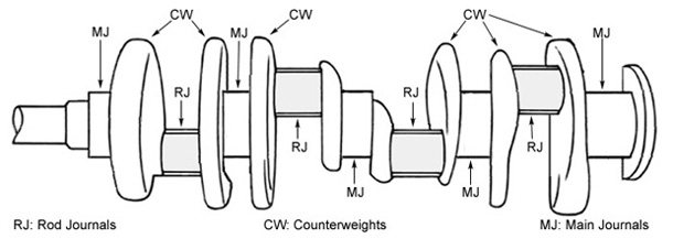
Crankshaft balancing is the term commonly used to describe changes made in the “counterweights” of the crankshaft (and other components in some cases) to compensate for the weights of the moving components including the crankshaft and the components attached to it (connecting rods, pistons, etc.). The counterweights are wedge or disc-shaped cylindrical sections positioned laterally in between the crank throws (each throw includes two connecting rod journals, generally in a continuous machined surface), and positioned rotationally opposite the throws (180° away) to “counter-act the weight” of the journals, rods, pistons etc. The counterweights are cast or forged in place when the crankshaft is formed, and the balance process is done by removing metal from the counterweights (usually by drilling holes) until their total is correct to compensate for the engine components.
It is necessary for any motor’s crankshaft to be in balance to operate without damage.
All crankshafts are balanced at the factory, but not to the same degree as would be required for racing, or even by a careful owner. The factory balance is only production-line quality, and can be improved upon by diligent effort. Parallel twins have used balance factors between 50% and 90% at various times. The unit-construction Triumph 650 twin (T120) used 85% successfully for many years.
This means that the amount of “extra” (irregular, and not structurally necessary) weight carried by the counterweights is equal to:
100% of the rotating weight + 85% of the reciprocating weight
The 85% factor has proven itself
over a long period of time as providing reasonable freedom from vibration,
excellent component durability, and acceptable rider comfort. However,
it is not, and cannot be completely successful in compensating for
the weight of the internal reciprocating components, as I will attempt to explain.
The purpose of this Paper is not to
explain how motors are balanced, but to discuss in part why balancing
is not easily accomplished, and to explore why even the most accurate
balancing job is only partially effective.
Balance Weight Placement
The extra weight for both balance and inertia purposes is contained completely in the crankshaft assembly.
Ideally, each counterweight should carry the imbalance of its adjacent journal and rod. In a parallel twin a total of three weights (each crank throw’ balance weight, plus the center flywheel) @ 12.5% of the total balance weight each on a V8 two-plane crankshaft), but not all internally balanced motors have the compensating weights adjacent to the components they’re adjusting for; many have NO center counterweights - all the balancing is on the outer weights. |
Each crank throw is eccentric weight, even if perfectly balanced (since the balance factor is never 100%). Even those with fully counter-weighted cranks don’t have ALL the out-of-balance forces self-compensated, since (usually) a percentage of the reciprocating weight is left out. This means that there will be some bending and flexing caused by the rotation of the eccentric weight as the crank rotates normally. | |
|
The “balance factor” is AT BEST a compromise, and partially suppresses vibration at some RPM and power/vacuum levels. Pictured here is a Triumph crankshaft. Click the picture for a larger view.
This means that the crankshaft is subject to bending forces from both directions all the time, even when the motor is in a favorable RPM range (where the 50% factor is most effective).
One method of correcting this, and converting an externally-balanced motor to internal balance, is to remove some metal from the counterweights, and substitute a cylindrical slug of a much heavier metal. The substance of choice is “Mallory metal”, an alloy of tungsten (symbol: W;); “Densalloy” is another.
The key is the relative density of the “slug” material vs. the steel or iron it replaces. Mallory metal is approximately 2-1/3 times as heavy as steel, so every piece removed from the counterweight and replaced with Mallory metal adds 1-1/3 of the weight of the substituted piece (e.g.: remove 120 grams of steel by drilling, fill the hole with Mallory metal, the Mallory metal slug weighs 280 grams, so the weight added is 160 grams. If enough steel is removed and replaced with Mallory metal, the counterweights will now be sufficient to balance the components without added eccentric weight outside the engine block. However, Mallory metal is extremely expensive.
A much less expensive, but more labor-intensive, substitute is lead (symbol: Pb) or (for those who believe in taking risks) mercury (symbol: Hg). However, it's highly toxic. Lead is much heavier than steel, but not as heavy as Mallory metal, therefore a larger volume of lead must be substituted for steel or iron in the crankshaft.
For example, if the equivalent lead weight would have to be 75% more volume than Mallory metal to make up the same imbalance: if 4 slugs 1/2” X 1” of Mallory metal were used, you’d need 7 slugs of lead, etc.
Component Definitions
The entire crankshaft assembly must
balanced (with the exception of certain rotating components marked
* in the list below). For this illustration, we’ll assume that the motor
in question is independently (internally) balanced; this means that all
compensation for the weights mentioned above is made to the crankshaft
itself, rather than to external components. The classic calculation requires
dividing the motor’s crankshaft and related components into the
two separate categories: rotating weight” and reciprocating weight”.
Rotating Weight:
» the crankshaft
» the oil volume of any hollow passages in the crankshaft
» the rod bearings (+ dowels, if any)
» the lower half of the connecting rod(s), including the caps & screws
» * any radially-symmetrical accessories attached to the crankshaft
directly, but external to the crankcase (cam drive sprocket, damper, pulley,
flex plate, flywheel, fasteners, etc.), that are inherently zero-balanced,
and have no intentionally eccentric weight distribution
Reciprocating Weight:
» the piston(s) & piston components, including pins, rings &
locks (+ piston pin bushings, if any)
» the upper half of the connecting rod(s) (except piston pin bushings, if
any)
However, a closer analysis of the
components quickly shows that there are actually three categories,
not two: pure rotating weight, pure reciprocating weight, and hybrid weight.
Classifying the connecting rod’s
upper and lower halves as reciprocating or rotating is not completely
accurate. The rod’s pin eye does reciprocate, but the rod’s absolute upper
end (including the material closing the top of the eye), and the rod beam
between the pin eye and the crankshaft’s rod journal follow different and more
complex paths. The rod’s big end does rotate, but only the imaginary line
marking the contact with the crankshaft’s rod journal is pure rotation,
the rod’s big end actually oscillates as well.
Let’s define pure rotating motion as
motion which exactly follows the position of an imaginary point on the
circumference of a circle, the diameter of which is the stroke length".
These components never come to a complete halt while the crankshaft is rotating and never change direction. They vary speed directly proportionate to crankshaft RPM.
Let’s define pure reciprocating motion as bi-directional linear motion; accelerating from fully stopped @ TDC, traveling down, slowing &
stopping @ BDC, then reversing and accelerating in the other direction,
slowing & stopping, etc.. These components come to a complete
halt twice in every crankshaft revolution. The speed of each cycle varies
in direct proportion to crankshaft RPM. The speed at different points in each cycle varies with the ratio of the connecting rod length to the stroke length, and crankshaft position; their direction reverses twice (up to down) during each crankshaft revolution:
at TDC (0°) and BDC (180°).
Let’s define hybrid motion as motion varying speed with the position
along the rod’s length as well as engine RPM, but
vary direction based on crankshaft position: no lateral movement @
TDC or BDC. Its movement is in the same direction as the crankshaft, and has highest velocity when the rod’s beam axis is @ 90° to the crankshaft throw,
which will occur between roughly 72° and 78° from TDC, depending
on the rod ratio (not 90° from TDC).
A: Pure Rotating Weight
» the crankshaft, etc. as described above
» the connecting rod bearings & dowels (if any)
B: Pure Reciprocating Weight
» the piston(s) & piston components, including pins, rings &
locks (+ piston pin bushings, if any)*
C: Hybrid Weight
» the connecting rod beam
The Rod Path
Material closest to the center
of the piston pin almost mimics the piston pin - its movement is
reciprocating plus a small oscillation back & forth. Its path is a long,
narrow irregular semi-ellipse with the minor diameter equal to the
amplitude (span) of oscillation, and the major diameter equal to the stroke
length (see #1 in the illustration below; the actual elliptical path would be irregular,
and asymmetrical re motion away from TDC vs. BDC). Points farther down the rod’s beam
and closer to the big end (see #2-4) have greater amplitudes of oscillations
(minor diameter) added to the stroke length (major diameter), again forming
an elliptical path, but of greater circumference and more regular shape.
The maximum oscillation is a function of
the rod’s maximum angle of inclination to the bore axis, about 13 -
20° in most cases; this is determined by the rod to stroke ratio
(longer rods = smaller angle). The outer limit of oscillation is therefore
an isoceles triangle, with the apex at the piston pin centerline, and
the 2 equal-length arms diverging off downward at twice the rod inclination
angle (26 - 40°). The width of the triangle’s base is the maximum oscillation
span or amplitude (the minor diameter of the ellipse), which is determined
by the triangle’s height, a function of the placement along the rod’s
beam axis of the point in question.
The beam closest to the piston pin (see
#2) has an minor diameter amplitude almost equal to zero, plus a major diameter equal to the stroke length
- almost a straight line.
The beam closest to the rod journal (see
#5) has an minor diameter amplitude almost equal to the stroke length
laterally, plus a major diameter equal to the stroke length
- almost a perfect circle.
This means that the shape of the movement
of each gram of weight, the speed of motion, and the distance traveled
per revolution of the crankshaft all partially depend on its exact position
along the rod’s beam axis, as well as the rod to stroke ratio, and
the absolute length of the rod centers.
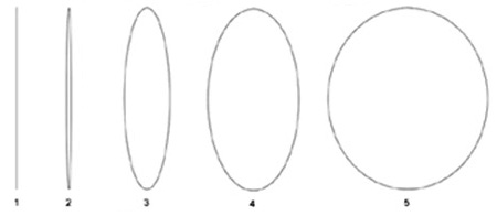
In the illustration (below, right), the motion
of several points on the rod’s beam are depicted. Each point would
travel the circumference of the shape shown during one rotation of
the crankshaft, arriving back at the top @ TDC each time. |
#1 shows the motion of a point
on the rod’s beam axis centered in the pin eye - the motion is completely
reciprocating. The major diameter for all ellipses shown is the stroke length
(here shown at 4.00), but since there is no oscillation there is therefore
no rotation, and the minor diameter (the width) of the ellipse is 0 - the
shape is a straight line.
#2 shows a point slightly below point #1 along
the rod’s beam axis. The minor diameter is about .10, representing a small
back & forth oscillation. |
|
|
#3 shows a point below point #2 along the rod’s beam axis. The minor diameter is about 1.00", representing a larger back & forth oscillation.
#4 shows a point slightly below this point along the rod’s beam axis. The minor diameter is about 2.00”, representing a path with much more rotating motion.
#5 shows a point almost at the big end of the rod, just
above the upper rod bearing. Here, the minor diameter is almost the stroke’s full length of 4”.
The next logical step down the rod’s
beam axis would, of course, be pure rotating weight, forming an ellipse
with the minor and major diameters at stroke length - a circle, the exact path of the crankshaft’s rod journal.
Rod Length and Ratio
All methods
involve separating the rod weight into reciprocating weight
vs. rotating weight by suspension of the rod(s) by
one end and weighing the other, carefully keeping the beam axis exactly
horizontal. The process is then reversed, giving the weight of the opposite
end. The total (of course) equals the exact weight of the rod.
However...
this makes the separation of reciprocating vs. rotating weights dependent
on the center of gravity , which is NOT a relevant factor for
balancing purposes. The exact center of the rod journal is pure
rotating weight (no rectilinear motion), whereas the pin
eye is pure reciprocating weight (no rotational motion). If
you stretched a rod by 1 in the exact balance center (without adding
any weight), the suspension-derived weight & proportions would not change,
but clearly the effect of the new rod on balance would change, because
the point of distinction between the reciprocating and rotating ends
is at the geometric center, not the center of gravity, which has nothing to do with predicting what effect a specific molecule in the rod is doing, and how best to compensate for it.
The position on a rod beam that has exactly 1/2 of the characteristics of each is located at the geometric center - because the center of gravity A giant chunk of lead hanging off the rod bolt will certainly change the rotating end quite a bit, but according to the “classic” model it also changes the reciprocating weight, and reciprocating weight percentage, because it moves the C-of-G. Since the big end is always much heavier than the small end, the center
of gravity will only begin to locate at the geometric center (50% of the
center to center distance) in a rod of infinite length ; shorter
rods will tend to have more bias between the C-of-G and geometric center.
Therefore, the absolute length of the rod (as well as the rod ratio) has
an effect on balance.
This (partially) explains why some factors
work better on some motors. Motors with higher n values (long rod,
short stroke, rod-to-stroke ratio in the 1.75 - 2.1-1 range, thrust angle
13-16°) have lower out-of-balance forces: the mostly linear upper
end of the beam walks back and forth through a smaller range, and its
maximum angle from vertical is smaller. Lower n value motors’ (short
rod, long stroke, rod-to-stroke ratio in the 1.45 - 1.75-1 range, thrust
angle 17-20°) rod beams swing through a greater arc as the maximum
deflection from vertical is greater - more of the force is vectored at
the cylinder wall (rather than at the crank throw). This affects selection
of balance factor. In my opinion, the separation (and assignment of weight
fractions to rotating vs. reciprocating) MUST include some compensation
for the length of the rod (as well as the rod to stroke ratio). An interesting
experiment would be to see where the mathematical center is (50% of center-to-center
distance; approximately 3.38 from either end of an RB 413, 426W or 440
rod) vis-a-vis the balance point derived by the C-of-G (suspended) method.
Geometric Center Rod Balancing
The “suspension” method assigns weight to small end vs. big end based on center of gravity; if you hung the rod in mid-air by a thread, and gently lowered it on 2 scales, the only point of suspension where it would hang horizontally is at the CG. If you tried to suspend it at the geometric center (50% of center distance) the results would be very different; the big end is always much heavier.
To weigh each end based on the geometric center: find and accurately mark the center point with a sharpie, etc. Build/find a waterproof container (C#1) 6” deep, 4” × 4” across, with upper walls exactly square & horizontal. Build/find a 2nd larger waterproof container (C#2) 2” deep, 6” × 6” across. Weigh C#2 on a gram scale and record. Place C1 with the upper edges exactly level in C2. Fill C#1 exactly to the top with clean water. Suspend the rod from the pin eye so that the beam is exactly vertical. Very slowly submerge the rod in C#1 up to the marked centerline.
If Archimedes was right, the water overflow volume is exactly equal to the volume of the submerged rod mass. Set C#1 & the rod aside. Weigh C#2, and subtract the empty weight. The remainder is the weight of the water in grams (water: 1 cc = 1 ml = 1 gm; isn't the metric system wonderful?). Multiply by the specific gravity of steel (approximately 7.93 as “rolled steel”) to get the actual 50% geometric-center derived weight of the rod's big end. If curious, do the other end the same way. If not curious, just subtract your result from the total weight.
These results will be very different from the weights produced by the suspension method.
Factors Affecting Balance
Motors run at high speeds frequently have extra
weight added, raising the factor. There have been many formulae
published to calculate the exact amount of adjustment to make to the
crankshaft to compensate for these factors. The adjustment is usually
made by removing metal from the counterweight or cheek directly opposite
the center of an imbalance caused by excess weight. Of course, it’s also
possible to add weight, but this is more complex and not generally the first
choice. If a known and trusted factor is used, the level of component reliability and comfort is improved. However, even excellent application of the wrong factor
may cause very unsatisfactory results - don’t be creative! Actually,
no formula is correct, some just come closer than others, by the
empirical method - they’ve been tried & adjusted by experiment.
All formulae are compromises based on motor details, but
also including such dimensional & physical factors as:
» Rod to stroke length ratio: small ratios (long stroke, short rod)
have higher out-of-balance forces.
» Firing order: a parallel twin is normally 360° with evenly disposed strokes between the two cylinders. However, Honda (and others) have made parallel twins with cylinders firing at 180°, and existing 360° designs have been converted to alternate firing orders such as 90°, 76°, &c.
» RPM range normally used: a wide range must be more forgiving of
bad spots. The calculation must be made for the entire range, not
just the power curve (except for racing).
» Amount of power developed: if necessary, the durability of the
motor is given preference to the driver’s comfort.
» Tolerance of vibration: how long will the machine be ridden? By
whom?
» Type of engine mount: solid? rubber? how many points of attachment?
Mathematical-based formulae using
only conventional factors will never predict accurately how
well a given motor will run, even at a given RPM, because the dynamic
forces aren’t limited to reciprocating vs. rotating weight. The forces
acting on the rod & crank-pin (mass inertia) are not only the reciprocating
weight (as listed above), but also the forces present in the cylinder
and combustion chamber above the piston. This Paper brings to the reader’s
attention how complex the subject is, and cautions them to research
the subject very carefully before balancing their motor.
Dynamic Factors; Pressure
Acting as Weight
The behavior of the gas in the combustion
chamber alters the effective (apparent) weight of the piston. The
gas experiences changes in density, volume temperature & pressure
continuously during the motor’s operation due to various factors. The
following text briefly discusses some of these factors, and the changes
they cause in apparent piston weight.
If the motor were cycled without vacuum,
compression or combustion present (the piston acting only as a weight),
the piston’s inertia would resist movement at all times (Newton’s laws
of motion), whether the rod be going up or down. This would have the
effect of reducing the apparent weight on the 2 down-strokes
(intake and power) and increasing it on the 2 up-strokes (compression
& exhaust).
However, when we add the dynamic effects
of vacuum, compression and combustion pressure, the effects are radically
altered, and they change not only as the details of the motor’s construction
change, but also as the crankshaft rotates, and the demand (throttle
opening & vacuum), RPM level and volumetric efficiency of the motor
changes.
As these factors come into play, the piston’s
apparent weight (and its effect on the crankshaft)
may increase dramatically, completely vanish, or become a negative
weight.
Let’s call the effect on the piston’s
apparent weight caused by the cylinder’s internal pressure fluctuations
pull. Pull can be positive (simulating adding physical weight
to the reciprocating components) or negative (subtracting weight),
and can act in either direction (up or down). Pull acts on the
rod and crankshaft assembly in the same way as the actual weight of the
reciprocating components themselves, but not at the same time, not continuously,
and varying in degree based on the construction and size of the motor
and its operating conditions. Even at the same speed, the degree of successful
compensation for out-of-balance forces will vary dramatically with throttle
opening. The motor will strangely vibrate as the throttle is opened, causing
the driver to fear broken mounts, bent driveshaft, etc., but the vibration
goes away as the throttle is closed again. Compare these effects throughout
the engine’s 4 cycles of rotation: |
Example 1
A motor with 12-1 (static) compression ratio
cruising, partially open throttle, 4000 RPM |
Stroke |
Piston |
Effect |
Comment
|
Intake |
Down |
Drag |
The piston’s pull (resistance to movement, as it affects
the rod) is high, as the cylinder is only partially
full (low VE, or volumetric efficiency, expressed in % of full displacement),
and is still under partial vacuum (15 psi) due to the small throttle
opening. This means that the rod sees a heavier piston than
the actual component, but only during this cycle and conditions. |
Compression |
Up |
Load |
Pull is low, as the low VE means only a small volume
of mixture is present to be compressed. However, cylinder pressure
is still higher than would be the case in a motor with lower CR. The
rod sees a slightly heavier piston than the actual
weight. |
Power |
Down |
Load |
Pull is low due to only a small volume of mixture
being ignited, but at a high ratio due to static CR. The pressure of the
expanding gas makes the piston’s weight go down past 0 and into positive
force on the rod, even with this low power level. The rod sees a lighter
piston than the actual weight. |
Exhaust |
Up |
Load |
Pull is probably very low, due to the low volume of
gas to expel. The rod sees a slightly heavier piston than
the actual weight. |
Example 2
The same motor, same speed, but wide-open throttle
|
Stroke |
Piston |
Effect |
Comment
|
Intake |
Down |
Drag |
Pull is less than with partially-closed throttle (above,
#1) because the higher VE means lower vacuum (as low as 0 psi under
ideal conditions at the torque peak) resisting the piston’s downward
motion. Piston weight will be neutral (pull = 0, reciprocating weight
will be the only force) if the vacuum is 0 psi, but pull will occur and
rise with the vacuum if VE is not 100%. The rod sees a slightly heavier
piston than the actual weight. |
Compression |
Up |
Load |
Pull is highest here, as the cylinder is nearly full, but
resistance on the compression stroke is very high. If the piston
diameter is 4.00 (360), the piston’s area is 12.57 square inches, so the
200 psi present during compression will exert a force of 2500 lbs.
on the piston! Nearly 100 VE (open throttle, demand almost completely
satisfied) means that cylinder pressure will be much higher than in
Example 1 (above). The piston weighs much more on the compression stroke
during full throttle than cruising. The rod sees a much heavier
piston than the actual weight. |
Power |
Down |
Load |
Pull is much less (high negative number). The 700
peak psi present in the cylinder as the mixture burns subtracts 8800 lbs.
from the reciprocating weight, leaving a huge negative number, and
the crankshaft is momentarily but very badly out of balance. The rod sees
a much heavier piston than the actual weight. |
Exhaust |
Up |
Load |
Negative pull is higher here than in the other Exhaust examples,
as the high VE means the cylinder is nearly full of gas. The resistance
offered by the gas increases the piston’s apparent inertia. The rod
sees a heavier piston than the actual weight. |
Example 3
The same motor, same speed, but with throttle snapped shut
|
Stroke |
Piston |
Effect |
Comment
|
Intake |
Down |
Drag |
Pull instantly jumps, as the cylinder is now almost completely
empty (VE approaching 0). Vacuum (which may reach 25+ psi) acting
on the piston’s area will exert a drag on the rod of 314 lbs. This
is why race motors break as they cross the finish line (it’s called
bringing the motor down against compression) - the inertia of the
piston weight alone would be safe, but the inertia + vacuum is enough
to either pull the dome off the piston, or pull the rod in half. The rod
sees a much heavier piston than the actual weight. |
Compression |
Up |
Load |
Pull is a small negative number, less than Example
1 as the VE is lower. The rod sees a slightly heavier piston
than the actual weight. |
Power |
Down |
Drag |
Pull is a smaller negative number than Example 1,
same reason: lower VE. Combustion pressure may be less than the frictional
drag of the piston, so the rod sees a slightly heavier piston than
the actual weight. |
Exhaust |
Up |
Load |
Pull is lowest here, even smaller than Example 1 - even less
gas to expel. The rod sees a slightly heavier piston than
the actual weight. |
Dynamic Factors; Piston Ring Drag
The piston rings are held against the cylinder wall by two forces: radial tension (“springiness” of the metal), and compression or combustion pressure above the piston.
The radial tension is pre-set when the ring is manufactured, and slightly altered when end gap is set; it will also decay over time.
The compression and combustion pressures are more complex, and ring drag will vary depending not only on which direction the piston is moving and on which stroke the crankshaft is on, but also on relative vacuum and power. |
Ring Drag vs. Engine Function |
Stroke | Effect |
Intake | Rings are held (weakly) against the top of the groove by vacuum, balanced against radial tension. WOT = low vacuum, etc. |
Compression | Rings are held against the bottom of the groove by cylinder pressure (compression only) + radial tension. WOT = higher pressure because cylinder contents larger. |
Power | Rings are held (strongly) against the bottom of the groove and out against the cylinder wall by combustion pressure + radial tension. WOT = higher pressure because cylinder contents larger. |
Exhaust | Rings are held against the bottom of the groove by residual exhaust gas pressure + radial tension. WOT = higher pressure because cylinder contents larger, more exhaust volume. |
Dynamic Factors; Motion vs. Direction
The reciprocating components of a
V configuration behave quite differently from those of an single-cylinder,
in-line or opposed (180°) motor. Using the standard V-8 90°
motor for example, let’s begin about mid-stroke (120° BTDC) with
both pistons on a single crank throw (but on opposite cylinder banks)
rising towards TDC. Both pistons (and the other reciprocating components,
as listed previously) are moving in the same direction (even though
not at the same speeds). However, as the left bank piston reaches 90°
BTDC the right bank piston has stopped at TDC. As the
left bank piston reaches 91°, the right bank piston is at 1°
ATDC (relative), and has begun to move down . The two pistons
will continue to move in opposite directions for 90°, until the
left bank piston reaches TDC, after which both pistons will be moving
down.
A similar effect occurs approaching &
passing BDC. The relative directions of the pistons is the same, but
the exact positions are different due to the difference in piston speed
at the bottom of the stroke (the TDC motion vs. BDC motion speed differential
and exact piston position are functions of the rod-to-stroke ratio).
Only at 45° from TDC and BDC are the 2 pistons on the same crank throw
in the same absolute position.
From left bank piston position 90°
BTDC to TDC and 90° BBDC to BDC, the left and right bank pistons
are moving in opposite directions.
The selection of the V angle itself
adds another complex factor to motor design. The narrow V angles (60°,
etc.) have a relatively short period in which the reciprocating
weights of the two cylinders are moving in different directions - the
same as the V angle (60° is only 16.67% of the full 360° rotation
of the crankshaft). However, the out of balance forces are relatively
high, and balancing is generally successful only over a narrow range of
engine speed. As the V angle widens (90°, etc.) the periods in which
the reciprocating weights are moving in different directions increases
(90° is 25% of the full rotation of the crankshaft), which appears to
make the problem worse, but the wider V angle motors appear more tolerant
of wider and higher RPM ranges, and the net effect is an improvement. However,
these motors generally require a wider engine bay for clearance,
as the banks are spread apart. This is one of the positive factors favoring
a V-6 - it’s not only shorter (by 1 cylinder and crank throw) than a V-8
with the same bore & stroke, but using the common 60° bank separation
angle it’s also substantially narrower across the cylinder banks (but slightly taller top to bottom).
In addition, the material in the rod’s pin eye (small end) above the center of the piston pin, as well as the rod bearing cap, are always oscillating in the opposite direction from the rod beam (except at TDC & BDC, of course). Although minimal in their effect, they are part of the rod’s “swing” (oscillating) inertia, but reduce and modify the effects of the rod beam’s weight. This “overhang” weight is currently not factored into any balance formula or equation.
The bottom line is that
the physics and mathematics involved in how the motor operates are
far too complex to make a formula-based balance factor any more than
a reasonable compromise. These are only the factors that I’ve
personally detected, there are almost certainly more (of greater or
lesser effect). Once the factor has been selected, the remaining tasks
are accurately to record the component weights, and precisely adjust the
crankshaft to compensate. Your motor will last longer and be more pleasant
to drive afterwards.
My opinion: any motor that is out
& apart should be balanced wherever practical. Only give this
work to a shop of proven reputation and competence. Don’t try to be
an innovator in selecting a balance factor; use one that has stood
the test of time & experience: 50%. If you wish
to experiment, pattern yours after a motor very similar to yours (especially
with regard to stroke & rod length, piston gram weight, operating
RPM range, and compression ratio).
New:
Fair enough: "balance factor" is the percentage of the reciprocating weight added to the counterweight to compensate for secondary out-of-balance forces in an inherently un-balanced engine.
I repeat: even "the people who do this for a living", "the people who make the machines", etc. have demonstrated that the only successful balancing (where it exists at all) is derived from bitter experience. What is purported to be science, math, physics, rules-o-thumb are, in fact, deconstruction from known results working backward to find an explanation.
They are as accurate as saying "the last time I wore a blue tie I got fired, therefore I will not wear a blue tie so I cannot be fired".
Causation is evidently a complex concept - after all, the Supreme Court gets it wrong frequently.
I'd actually explain why the "math" doesn't work, but:
1. I'd be wrong
2. someone would be certain to "explain" how balancing is done (i.e., read absolutely none of the prior posts)
3. based on several previous attempts, no one reading it would grasp my argument
Perfect balance, where all forces are "neutralized" by opposing forces, is a function of engine design such as boxer etc. and is not even remotely possible in most designs and certainly not in a parallel twin. Some are better than others, an in-line 6 is better than a V8. An in-line 4 is terrible but the bad symptoms are scale-related and only impossible to live with above 2 litre capacity (something the auto industry has had to re-learn every 20 or 30 years).
The goal of balancing a parallel twin is to find the percentage of reciprocating weight (and defining that is, IMHO, something that is still done wrong) that results in a shaking force that the tuner finds acceptable.
But isn't the lowest force the best?
No - Norton didn't think so. The 850 is balanced to shake badly below its useful power range so no damage is done.
Acceptable can be the lowest amplitude internally (to protect the engine), lowest transmitted to the chassis (to please the rider), narrowest RPM range with higher amplitude (to make a wider range vibration-free), etc. These are all choices, there is no "best", and perfect balance is NOT POSSIBLE.
Perfect can also mean "extremely accurate execution using the highest standard of measurement and machine work", but this will not, can not, perfectly balance anything.
I think they did it in various percentages, and when they had something that worked they "analyzed" it backwards to get the 85%. In this case, and most others, "what works" trumps "what does the math predict" - as you said. In some cases I suspect the error (difference between 2 methods) is very small, especially where the rods have good uniformity for a long period.
The article is one of 2 (the other is H-D targeted), but has the most content although it is V8 oriented and not too useful for a parallel twin. I'm working on a 3rd version for these and will add it to my tech directory when available ( http://victorylibrary.com/brit/brit-tech.htm ).
Unless you have some of the following changes, I wouldn't even attempt to second-guess a known-to-be-safe-&-effective factor such as 85%:
1. new and very different rod ratio (10% change minimum, such as a Norton 89mm crank with Norton rods - the Triumph ratio is 2.01:1, the Norton is 1.677:1).
2. very heavy reciprocating components (steel rods such as Carrillo)
3. very high RPM use (de-stroked)
4. (perhaps) supercharged/turbo with high boost
5. a different method of mounting the engine, such as the pre-unit (which used 71%). The chassis picks up vibration from different points than on a unit model, and transmits it differently (suppressing some, re-enforcing some) - this isn't fact, just my guess, since the rod weights are very similar and the geometry (82mm, 6.50" rod) is identical to the unit. I have a gut feeling that the ideal T140 balance factor should be different due to the rod ratio change (down to 1.859:1), but the other changes (OIF, 5 speed, shorter cylinder) may have masked or reduced the effects.
I also have a suspicion that longer rods reduce vibration (lower thrust angle = lower secondary force), and also reduce the need for finding the "ideal percentage", whereas an engine with 1.5:1 ratio (and therefore very high shaking force in relation to its component weight) might take a year of development to find a good number.
Highest rod ratio? The 1966 Repco-Brabham V8 (yes, Jack Brabham), based on the Oldsmobile factory aluminum block (3.50" X 2.80" = 215", like the Rover), used a 6.30" rod (up from 5.66") with 2.20" stroke, for a 2.864:1 rod ratio. They were stuck with the existing block deck height (rules and $$$), and shortening the stroke was needed to reduce size for class to 3 liter? That would make the bore 1/8" over: 3.625" X 2.20" = 181.64" or 2977cc.
The whole thing weighed 300 lbs.
|
|