|
|
 |
This article is an update to the first article that I published, in late 2001, on my experiences in building offset crankshafts for Triumph twins. That article concentrated on the details and people that assisted in building my first all-welded crank. Since that time I have built many offset crankshafts for BSAs, Nortons and Triumphs. Each crank has been a little different, based on customer requirements, and there has been much learned along the way to improve the end product. I also discovered that camshafts can be modified but theres a huge risk; I recommend buying a custom cam in most cases. Updated information includes my experience with latest generation of cranks, breathing and better ways to modify Boyer-Bransden ignition systems to suit an offset-crank British twin.
Geoff Collins June 2007 |
Crankshafts |
The first crank |
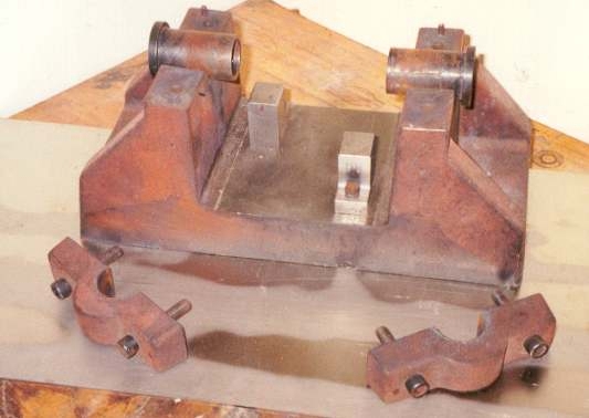
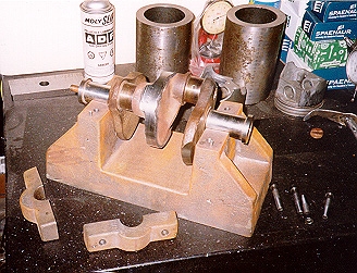
I became interested in building a 900 crankshaft for my 1970 Trophy in 1997 after reading various Classic Bike articles on the benefits of both 760 and 900 crankshafts. At that time I decided that everything Id seen, based on bolt-up assemblies, was not adequate or too expensive. Shown here: The fixture with |
|
|
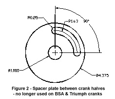
bushings, clamps and stops to position crank throws (left), Spacer plate between crank halves - no longer used on BSA & Triumph cranks (right). Click for a larger view.
Not everyone can afford billet-machined cranks, and for some engines, nothing was available with stock stroke and other dimensions. From day one I decided a fixture was required, along with other tooling, to build an all-welded offset crankshaft using stock components. The fixture was cast from Class 45 iron so that it could be used to keep crank journals perfectly aligned during stress-relieving processes. Slip-fit bushings and stops of different sizes are used for different displacements and types of cranks; Norton, unit and pre-unit BSA and Triumph twins. Even plain bush 500 Triumph cranks can be built.
I do little of the machining and welding, all work is done by experienced machinists and die-repair welders. I dont have the equipment or years of experience needed for a production-quality job. For example, once the fixture was cast, the only machining I did was to modify the fixture to make the drive and timing side clamps with a hacksaw and drill press to drill and tap holes. It was also part of the exercise to have others build the crank to determine a price that I could quote no matter what offset angle or crank was being built. Figure 1 shows the fixture with bushings and one set of stops that are used to set big end journals for accurate 72, 74, 76, or 90° offset on BSA and Triumph cranks. Different tooling is used for Norton cranks because their bolt-up assembly holes can be used to locate crank offset on a new flywheel. The first Triumph crank I built used one donor crank with a spacer plate for oil galleries between crank throws, similar to Figure 2. The stock flywheel was removed and the crank was cut in half through the centre web. Spacing between drive and timing side journals was maintained. The crank was welded in the fixture to maintain alignment. |
Triumph cranks |
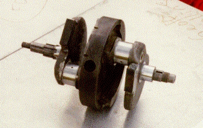
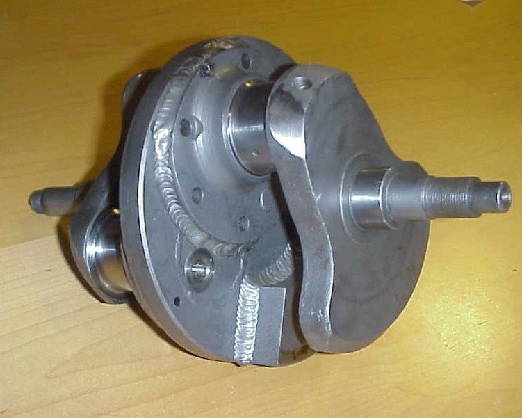
After the crank was welded, the centre section was machined, and the stock flywheel was welded back onto the crankshaft. Shown here: Welded crankshaft before flywheel is fitted. Bushings are shown on the ends of the crankshaft (left), The first crankshaft - original flywheel mounting holes |
|
|
are not used. Odd Mallory-metal counter-weights on crank cheeks added by balanced - they are required on Triumph and BSA cranks (right). Click for a larger view.
At this point the crankshaft rotated freely in the fixture indicating minimal distortion of crankshaft had occurred. The entire assembly was stress-relieved, all journals were checked and re-ground then the crank was balanced dynamically on computer-controlled equipment. Figures 3 and 4 show the resulting crank before stress-relieving and after balancing. In the current process, without the centre section, a large ring is cut in each mating face to provide an oil way between throws.
This original process, while it could easily be replicated, required too many machining operations and created problems for the welders. The crank is alloy steel while stock Triumph and BSA flywheels are cast iron alloy. Anyone familiar with welding two dissimilar alloys knows what can happen; messy welds with lots of surface irregularities. When the balancing was done a lot grinding and milling had to be done to reduce the stock cranks flywheel into something that could be balanced. In the end, the crank weighed about the same as a stock crank though it had less inertial weight. This bike did not accelerate as fast as anticipated but it was as smooth, as an air-head BMW twin. Time to change the process. |
Custom Flywheels |
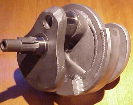
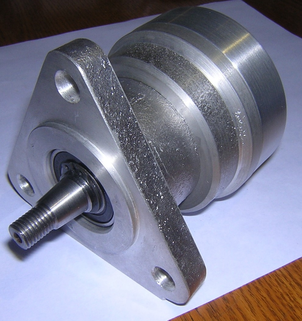
After the first offset-crank Triumph was running, and a number of people had ridden this motorcycle, I received a number of requests to build Norton cranks. Norton flywheels are huge, and also cast iron, so it made sense to machine a custom flywheel rather then welding and machining something based on the stock flywheel. Shown here: Norton crank with counterweights and sludge trap plugs |
|
|
before balancing and nitriding. Click for a larger view.
This new 4140 steel flywheel, similar to the alloy used for Norton cranks, and was smaller then the stock cranks smallest diameter (6.8). Flywheels were machined, the crank was welded together and counterweights were welded opposite to each throw. Crank was then stress relieved, ground and balanced. Sludge trap plugs are the same as used for Triumph or BSA cranks but most people did not want them as they were using an oil filter (recommended!). |
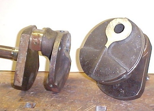
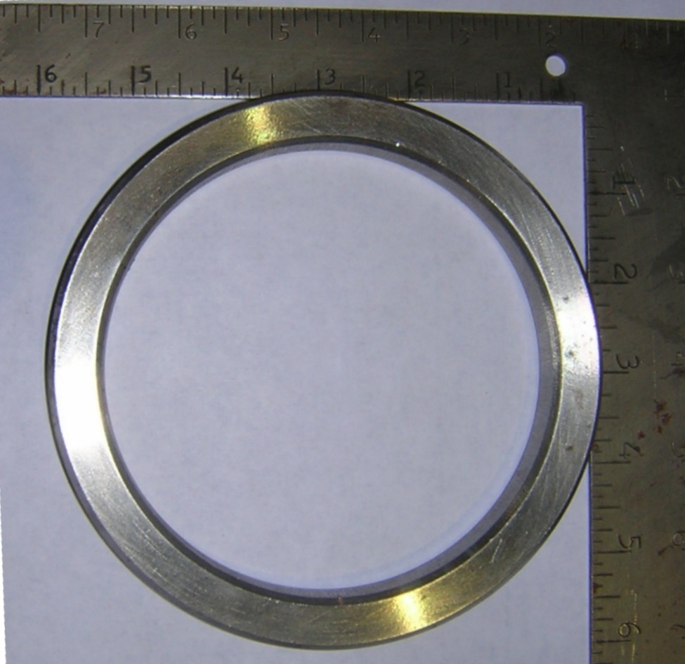
If this process would work for Norton cranks, then why not do something similar for Triumph and BSA cranks? The only way a custom flywheel could be created was to use two donor cranks, machining the face of each to match the other, then |
|
|
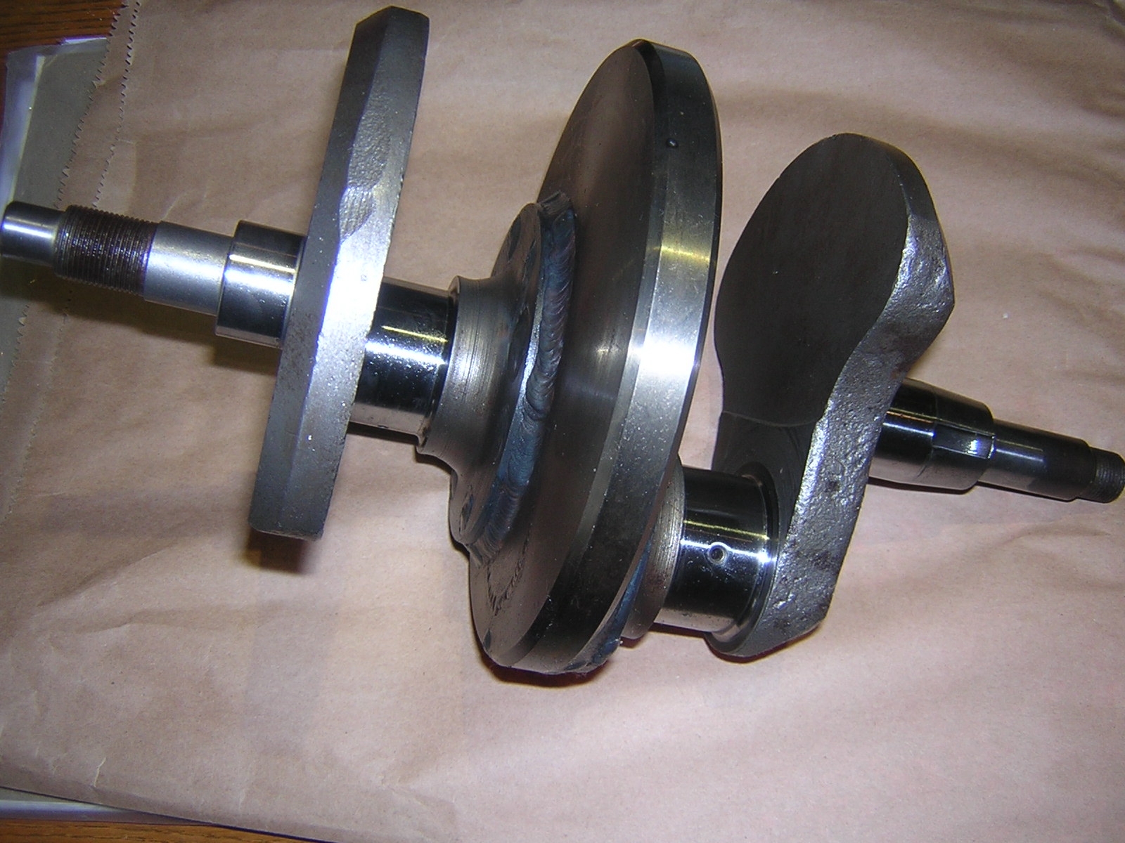
welding a small ring around the crank (the flywheel in Figure 7). Figure 6 shows the donor cranks before machining with Figure 8 showing the resulting welded assembly with counterweights. Shown here: Donor cranks before machining (left), Flywheel for BSA or Triumph, Lightweight Triumph crank (right). Click for a larger view.
The Triumph crank pictured weighs only 16.5 pounds and is smaller in diameter then the stock flywheel. The actual 'flywheel' reinforces the welding between the two crank halves which is buried under the flywheel. A centre-pin is also welded between two crank halves; this pin maintains alignment for weld assembly.
Using the new process, note only are the cranks are lighter then stock, but more importantly, they have less inertial weight; a 19 pound Norton crank can perform like a lighter 360° crank. This level of weight reduction, coupled with a 90° offset, can make a stock 650 Bonneville outperform a stock 750 Bonneville on all but top speed and still be far smoother then any stock machine. If a belt drive is used, an engine with an offset crank and twin carbs, comes close to air-head BMW smoothness. The first Triumph I built, with single carb, a slightly heavier flywheel and belt drive is still the smoothest machine that Ive built in the idle to 5500 RPM range using a 60% balance factor. Later cranks, using the lighter flywheel and a 50% balance factor vibrate more at idle but are smoother at higher RPMs.
Along the way the advice of various trade specialists has been included in the process. Crank components are machined, then welded, then stress-relieved before grinding. After grinding all cranks are nitrided to increase wear resistance followed by final polish of all bearing surfaces. The value of this was proven with the first nitrided Triumph crank. The engine was assembled by someone else, and this mechanic continued to assemble the engine even though the connecting rods were too tight. The engine seized. When it was taken apart the bearing shells were scored but the crank journals were unharmed. Since I have no control how an engine is assembled this step is critical insurance as I cannot warranty something that is generally made from used components that are more than 30 years old.
The balancers also provided the best advice. I continue having the counterweights machined but allow the balancers to cut them and weld them to the flywheel. They check the crank on their computerized equipment then determine how much weight is required and where to add it. This process makes a prettier looking crank with no holes drilled in it This also meant the crank could be nitrided and journals polished before balancing, instead of after. All crank journals are micro-polished after nitriding because they grow in size by a few ten-thousands of-an-inch and nitrided surface is not as smooth as original ground surface.
Ive also become more picky about donor cranks. Almost every Norton crank that I have received has been hammered at one end or the other, to assist in separating the cases. If theres a hammer mark, I can guarantee that that end is bent in some way. Norton cranks also have to be Magna-fluxed because many have small cracks between drive-side bearing journal and drive-side crank cheek. Fortunately, the cost of this is covered by reduced cost in making a flywheel and counterweights for a Norton in comparison to a BSA or Triumph crank. BSA and Triumph cranks usually have similar hammer marks, but since two halves are used, I can usually find two good ends that can be mated to make one good crank. |
Crank offsets |
The first article on offset cranks, written by Phil Irving in the early sixties, proposed a 76° offset based on the stroke and rod length of a 650 Triumph. His theory was that while one piston was at TDC the other would be at maximum speed in the other cylinder. Going further, formulas such as shown at right, using a scientific calculator, indicate compromise offsets of 72 (some Norton), 74 (750 Triumph and some Norton) and 76° (long rod Triumph 650). Each offset works best for different engines (see detailed information elsewhere in this booklet).
Balance angle = 90° minus the maximum thrust angle.
Maximum thrust angle: arc tangent, also known as tangent^-1 of (1/(2*rod length)/(stroke length)).
To do this on a scientific calculator: |
1. rod length [enter]
2. × 2 [enter]
3. ÷ by stroke length [enter]
4. invert (1 / X)
5. click [Inv] box, then [TAN]
6. subtract 90°.
result is offset angle
(information provided by Jeff Diamond)
|
Along the way other theories and formula have come out indicating that a compromise should be reached between the location of the moving piston in comparison to both TDC and BDC positions of the other cylinder. This results in an 80° angle for an 850 Norton. Other people that have built Norton engines for Daytona, have built 180° offset cranks with a centre main bearing to compensate for the huge rocking couple created by this large offset.
Since the cranks I am building are for street use, I continue recommending 90° as it results in perfect primary balance. Increased acceleration can easily be gained with a lighter flywheel, more then compensating for the benefit of maximum piston speed in one cylinder while the other piston is at BDC or TDC. For the street, whats better, a smaller diameter 19 pound Norton crank, or the stock 24 pound (or heavier) crank? I dont know how to make a comparison piston speeds and crank weight so I can only work with the smoothness factor. That doesnt mean I wont build a crank to any angle that someone requires, but do recommend that people determine how they will use the bike before trying to squeeze 1 or 2 HP that they hope to get from a strange offset.
Ultra-light weight crankshafts is another area that should be introduced. Racing Nortons are being built using 15 pound, light-weight cranks using exotic steel alloy billets. I have only seen images of these cranks, on the web, but have an idea how they are made. Since my cranks are made for street use, and primarily for smoothness, Im not looking to build anything less then 16 pounds for a BSA or Triumph, or 18.5 pounds for a Norton. That weight reduction, plus reduced inertial weight, gives an immediately noticeable result, even using a mild cam and stock bore and pistons. Anything lighter will bring back the vibration problems at some point in the RPM range that you are trying to eliminate with an offset crank. |
Crank Balancing |
Balance factor is highly dependent on two major elements; the frame the engine is mounted in and what RPM you want the engine to run smoothest at. My balancers can balance a crank to any RPM range where the smoothest result is desired. This may result in a buzz above or below this range | |
|
because the frame is now vibrating. This vibration is low in comparison to stock 360° cranks but still noticeable, especially through solidly mounted handlebars. Shown here: BSA A65 crank, 16 pounds and 6" in diameter (left) Norton crank before balance weights added. It will be about 19 pounds (right). Click for a larger view.
Triumph used anywhere from 55 to 85% balance factors in the fifties and sixties, looking for the compromise between acceleration and smoothness. Norton Commandos use 55%. My Triumphs and BSAs use ranges between 50 and 60% depending on RPM range that is requested. Ive built Norton cranks that use 45% and Ive seen articles suggesting 38% for a Norton crank with an 80° offset.
Since few people have reported back on the result of these different factors I cant speculate on what RPM range is best. No matter what is used, the bike is still far better then a stock crankshaft, even with offsets other then 90°. Ive built many Commando cranks for engines that will be mounted in featherbed frames. In a stock Isolastic mount, the balance factor can be the smoothest for the RPM range that the owner desires without worrying about frame effect while a similar engine in a BSA A10 frame might be best at 50%.
The figures below show the current generation of BSA/Triumph cranks and a Norton crank. The BSA/Triumph cranks will be balanced at 55% while Norton crank will probably use 50%. One critical area that is rarely mentioned when talking about balance factor is how the crank is balanced to reduce the rocking couple. Computerized balancing equipment notes that problem resulting in weight being added or removed from throws on either side. If someone wants to be more precise, the crank should also be balanced with timing pinion, washer and nut, and sprocket, alternator, washers and nut on the drive side. The balancers can balance within one gram, if required, in any direction. Normally, balancers need the rods, pistons, wrist pins, bearing shells and circlips for both cylinders. Pistons and rods are marked as to which side they came from along with installation direction of the pistons. Its useful to equalize the weight of the pistons and rods before the crank is balanced so they can be installed in any cylinder.
| |
Breathing |
The standard timed breather setup, used for BSA and Triumph engines, can still used, but it must be assisted by another breather line running from the timing hole (on a Triumph) or other similar locations on the crank case. One-way valves can be used, on the stock line, and on the new line, so that oil and air can only be blown out the line and not sucked back in. The best set-up is a direct feed to the oil tank with a separate line from the oil tank to the rear of the bike away from the rear tire. If a condenser is fitted in the breather line, ensure there is some way for it to drain back into the engine rather then to a low spot in the breather line.
Pre-unit BSA and Triumph engines can have a breather tap added into the cases below the magneto/distributor mount. A similar location can also be found on Norton engines. Additional breather holes can be added to the breather timing disk in an A7/A10 engine using a cobalt drill that can penetrate hardened steel. 1970 and later unit Triumphs, that use the primary chain case to increase crankcase volume, do not need special breather lines, as the volume of the chain case compensates for the problem of having pistons at different positions in the bore. |
Camshafts |
My number one recommendation is to have a custom camshaft made to suit the new valve timing interval. Megacycle Cams, or Johnson Cams, or various people in the UK, will grind a custom cam for an offset crank engine. Some suppliers are faster | |
|
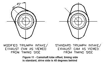
than others as these cams are not stock items. SRM Engineering in the UK is the only supplier that stocks an offset cam for unit BSA engines. Shown here is Camshaft lobe offset, timing side is standard, drive side is 45°s behind (left), and 67-357 BSA A10 cam, showing weld at one end where centre pin was welded that connects to other half of cam. All welding is done in heavy heat-sink fixture as heat control while welding between lobes is critical. Note hole in cam near left end for indexing fixture (right). Click for a larger view.
I have modified Norton and pre-unit BSA cams, originally with poor results, but now have a process and tooling that works. It was expensive experience.
It took many scrap cams and fixture modifications to get a result that I would sell. I had better luck with BSA A10 cams, and now use a process that involves a heavy cast 4140 steel fixture with indexing levers and other fittings. Its a complex process that I wont detail here. Its inexpensive but high-risk, but the only way to go with some engines where a good profile is not readily available, such as with BSA A10s, AJS/Matchless or a Royal Enfield twin (yes, they can be done too.)
MegaCycle Cams made the camshafts for my Triumphs, using instructions similar to Figure 10. After the engine was assembled, and cam timing checked, lobe positions were found to be within less than 10 of cam specification. One major advantage to using commercial cams is the range of grinds they offer as well as good, hardened alloy steel. I have tried re-hardening stock cams, and it can be done, but the risk that the cam warps is high. One Norton cam I received had a hardness of Rc15 where it should be greater then Rc45. |
Ignition Systems |
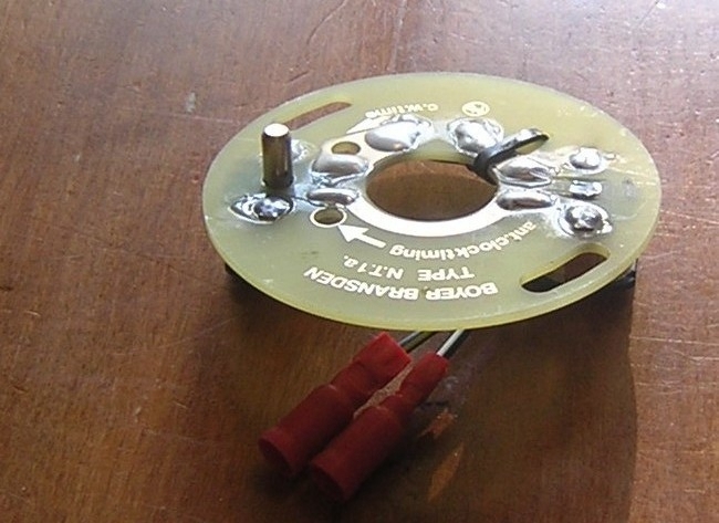
The first offset-crank Triumph that I built used two Boyer-Bransden ignition units with a modified stator that had four pickups. Advice at the time indicated that this ignition system required two magnets (on the rotor) passing by two pickups at the same time. This meant that a separate ignition unit was |
|
|
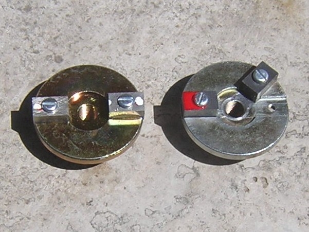
attached to each pair of pickups and each unit was firing on a single cylinder through stock 12 volt coils. Shown above is Modified stator with one pickup pin ground off. Installation, static timing setup and strobe timing follow Boyer-Bransden instructions exactly.(left), and Standard and modified rotors BSA/Triumph rotors shown. The red paint is used for static timing setup of timing side cylinder (right). Click for a larger view. Fortunately, there is a simple, less expensive way to do it, using one Boyer-Bransden kit. I modify two items; the rotor to move one magnet to match crank offset and the stator, cutting off one pickup pin to remove one waste spark. The instructions that Boyer provides for connection and timing are not changed except for one step; all timing must be done using the timing-side cylinder and timing-side magnet. |
The original offset-crank Triumph and the latest version with lighter crank; can you see anything different? The 1967 Triumph Bonneville is 650cc with 9:1 pistons, stock exhausts and a Megacycle 510 grind cam. This bike out-accelerates the 1970 750cc single-carb that has 8.4:1 pistons and the same 510 grind cam. The 1970 bike uses a |
|
|
60% balance factor while the 1967 uses 55%. The 1970 is smoother, and has a higher top speed but the 1967 accelerates faster and is smoother above 5,000 RPM. Cruising at 60 mph in 3rd gear, or a four-speed gearbox, is pleasant where normally a twin rider is hurrying into top gear at that speed.. |
Pre-unit ignitions |
Kirby Rowbotham, in the UK, sells an ignition unit that replaces the magneto or distributor of an alternator model. Shown here is a Kirby Rowbotham ignition unit; click for a larger view. This unit carries the rotor and stator of the ignition system. If running a pre-unit generator system, you must swap the stock Lucas unit for a more powerful Alton unit. The stock 60 watt generator is not strong enough to drive the | |
|
Boyer-Bransden unit and a halogen light that you'll insist on having to match the increased speeds you'll be running at night. Different units are sold for Triumph application and BSA/Norton with their tapered shafts for the drive gear. Always use a fibre drive gear that does not have the auto-advance unit unless the unit is frozen. Watch the direction of rotation - a stock Atlas or other pre-unit British engine uses a rotor modified for clockwise rotor rotation the same way a unit Triumph or BSA is setup.
|
What Does It Sound Like? |
Thats the first question most people ask about an offiset-crank British twin, not how it runs, or how smooth it is. As a simple comparison, with stock twin exhausts it sounds like an early Ducati desmo V-twin with the typical valve clatter of a British twin. With a two-into-one exhaust, its similar to a small-block V8 engine at a stock car track. My 1970 Trophy, with single carb and two-into-one exhaust turns the heads of car rodders; my 1967, with stock twin exhausts, sounds similar to an iron-head Sportster because of the valve noise. The bike still sounds British.
Conclusion
Theres enough information in this article for someone familiar with casting, machining, welding, heat reating and balancing to make their own all-welded crank. All power to those that decide to try it! The experience I relate in this article represents more then 8 years of building cranks, the experience and advice of many skilled trades, the delays, heartaches, sleepless nights and failures and successes that came along the way. Theres also thousands of dollars in custom tooling, some of which became scrap. Theres also the reality that the market is shrinking and many British twins are being built for show rather then every-day street use.
As a hobby, something far removed from my normal situation in a stressful business environment, I think it was worth the effort. Nothing pleases more then a hobby interest that also helps others to keep riding longer and more comfortably. Be prepared, when considering or enjoying your smoother, faster ride, to receive criticism and arguments from purists. British bikes have to vibrate! Its not original! I would never wreck a good crank to make something like that (most donor cranks are no longer usable in a stock engine)! Well heres my rant on the subject; why didnt the new Triumph organization use an offset crank in their 900cc Thruxton instead of their mild Bonneville cruiser? With lighter flywheel, counter-balance weights and a hot cam that would be a great bike
.
Geoff Collins
|
|