|
|
 |
Wedge Combustion Chamber Shape Breathing Improvement
The “as-cast” shape of the combustion chamber in Chrysler production heads is no worse than those of other manufacturers, but all can be improved. For “legal stock” classes, restrictive rules limit combustion chamber modifications to the valve seat area. The seats may only be modified to a very limited extent, and by machine tools only (no hand blending or radius permitted). The usual rule is a very shallow bowl (20 - 25° angle) surrounding the seat - no other metal removal is permitted. This is why expensive professional legal stock class head preparation does not address the work I will discuss here.
For street or bracket-racing motors, these restrictions don't apply, so another method of modification can also be used. Some simple math, lay-out, and die grinder work can add more breathing potential to your heads, without a flow-bench or templates.
Both the intake and exhaust seat areas can be modified, although the work is more effective on the intake side. In this discussion, I will refer to “valve” as if it were the intake valve, but the same method can also be applied to the exhaust side, if you wish. The effect on the exhaust is slightly different, as the efficiency is not improved to the same degree, but pumping loss is reduced a bit, and the chamber edge temperature will drop at the point of proximity.
This method will slightly increase your chamber volume, reducing the compression a bit. For conversion: cubic inches x 16.387 = cubic centimeters; cubic centimeters × .06102 = cubic inches.
Concept
As gas (fuel & air mixture) travels down past the intake valve seat, the relatively narrow throat & valve seat area widens abruptly into the full width of the chamber, a difference of more than 200% in area. However, the chamber wall on one side restricts and confuses the gas as it enters the chamber. The restriction occurs wherever the chamber wall is too close to the valve in any open position, but I will limit my comments and suggestions in this article to the chamber wall to one side of a valve seat, left or right (270° & 90° position) depending on which valve, along a line drawn through the valve guide centers in each head with the spark plug locations at the top. Alterations to the spark plug (0°) and quench (180°) areas are more delicate and complex, and no inference is to be drawn as to the effect of the modifications discussed here to these areas.
The improvement here is to change the shape and position of the wall in this area so that it not only allows more free flow, but also directs and stabilizes the gas as it enters the chamber. The term generally used to describe this improvement is a “relief”.
All valve seat, guide and compression milling work must be completed before you begin relieving.
Preparation
The first step is to get the correct tools. The preferred tool is a die-grinder, Dremel, etc. equipped with a ¼” carbide or abrasive bit. An air die-grinder is fastest (also most likely to cause mistakes). An electric die-grinder is fine (Sears Craftsman Industrial model is an excellent buy for the money), just a bit slower. A Dremel is going to take longer due to the smaller motor. The best bits are carbide (don't bother with “high-speed steel”, etc. as they will quickly become dull), and are available in a wide variety of shapes. I use a ¼” cylindrical bit for roughing out work. They're expensive, but unless you drop it, it'll last a long time and cut through iron like cheese. For small curves, radii, etc. you may find abrasive bits helpful; I use ¼” ball & ½” cone shapes. “Cratex” and abrasive cartridge rolls of various sizes are useful for finishing work (use low speed for these). You will not need finer polishing material than 240 grit, as a satin-smooth finish is quite sufficient. For best control, keep the speed down - this prevents the tool from bouncing and digging in.
If the rocker stand, water jacket, accessory bracket, spark plug and valve cover bolt holes, etc. are plugged or masked, clean-up will be easier. Also mask the exhaust seat, port and guide holes if only modifying the intake side.
You must wear eye protection when doing this work, for obvious reasons. Be sure to use ear protection as well (shooting muffs, etc.). Wear a dust mask, abrasive dust is hard on the lungs.
Lay-Out
Begin with a clean gasket surface. Cover the adjacent wall (left or right side, depending on the valve) of each chamber with a layer of duct tape; use a rolling pin, etc. to make sure it's firmly attached. Take a head-gasket of the same type which will be used to assemble the motor (used, in good condition OK), and very carefully position it on top of the head, being certain to line up the bolt holes all around. Now, trace a line following the inside bore surface of the gasket on all 4 chambers. Cut through the tape along this line using an Exacto, utility knife, single-edge razor blade, etc. Carefully peel back the tape inside the chamber, and discard. Only the exposed surface may be relieved, and the remaining tape will offer good protection against accidents. If you prefer, use Dykem, etc., coating the cylinder top surface as per product directions. Spray paint may be substituted - lightly spray the top surface from directly above. Wait 5 minutes, then remove the gasket. In the case of Dykem, you now have a line separating the area needing work from the area that must not be touched. If paint is used, only the painted area may be cut. You may find it useful to apply duct or masking tape to the head-gasket pattern to protect it from accidents. The area inside the gasket is the absolute limit to the reliefs in any case, but please note that not all this area will be cut.
When trying to decide how extensive to make your reliefs, remember that it is easier to remove metal than to put it back!. If not sure, do a mild job - you can always do it over when the heads are off. The most frequently made mistake is doing the 1st few chambers to the max, and not having the patience to do the remaining ones to match it. Any relief at all is a big improvement, and the first metal you take off has the greatest effect.
When in doubt, go slowly. Generally, in Chrysler wedge motors (not poly or hemi) alternate pairs of valves (both intake & exhaust) are mirror images of each other (exactly alike, but reversed in adjoining chambers such as # 1 & 3, etc.), and must have matching but opposite-handed reliefs. Except for this mirror-reversal, all 8 reliefs must all match as closely as possible, not only for flow, but to keep chamber volume changes consistent throughout the motor.
To avoid losing your “mirror” effect, I suggest working alternately on all 8 seats; mark out each cut on all 8, then begin the actual metal removal. If you cannot remove all grinding marks, remember that those running in the same direction as the gas flow are relatively harmless, but the ones that cut across this line are bad. If you must leave any surface roughness, end with light strokes in the same plane as the gas flow (parallel to it).
Dimensions
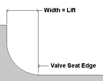
Generally, an intake relief width equal to the valve lift is safe; take the figure from the cam specs: .484”, .509”, etc. For an exhaust relief, a lower figure equal to 60% of the lift is most effective. Any smaller figure will be less effective, but still worth doing to the same consistent but lesser dimension. If a seat is already more than this distance from the chamber wall, leave it alone. In areas where the distance is less than this, mark the area with a china marker, scribe, etc. If the mark falls outside the bore or head-gasket limit, end the relief at the closer of the 2 - do not extend the relief beyond the bore or into the gasket surface. In some cases, extending the relief into these areas is useful (such as 1.88” exhaust valves in Max Wedge motors), but these are special cases, and beyond the scope of this article.
Quick rule of thumb (only applies to some engines, YMMV): if the intake seat is closer to the edge of the chamber wall than the lift, moving the wall back may help.
If it's already more than that, leave it alone.
Generally the new shape is an arc centered on the valve head and concentric, but larger.
If you're sure that the port swirls, offset the wall relief in the same direction by 1/16" or more.
If not, offset it in the direction of the stem axis at: angle × .005" (15° angle = .075",etc.)
What has not been explored enough: if the chamber wall is already at the bore edge, when is moving the guide over (closer to the bore center) helpful, and how much?
I've read of detectable results from even .030" re-location, but that was on a 4" bore engine with a 2.02" valve touching the bore edge.
B/RB 906 Chamber | 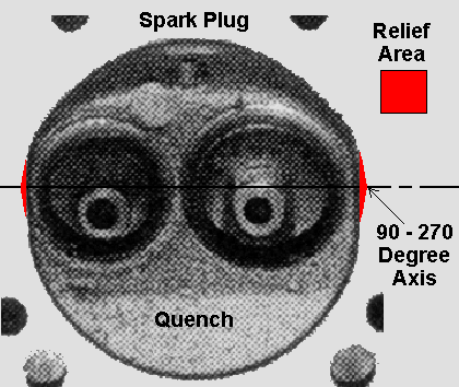 |
Use a valve guide pilot & cutter tool to accurately locate the edge of the intake relief. Set the cutting tip at the valve head radius + the lift distance. For example: with a 2.08” valve, the radius = 1.04”, intake lift = .509, set the cutter tip @ 1.549” from the center of the pilot stem. Lightly oil the pilot, and slip the tool into place. Rotate the tool slowly in the target area. As it sweeps past the chamber wall, press down hard enough for the tip to mark a radius on the surface.
If this tool is not available, use a piece of thin metal scrap securely taped to the head of a valve so that the edge extends past the valve head by the lift dimension. Lightly oil the valve stem, and slip the valve into place. Rotate the valve slowly in the target area. As it sweeps past the chamber wall, mark the radius with a scribe, china marker, etc. This will be the limit. Don't open the relief to the bore edge - the flow is disrupted if it expands too rapidly as it leaves the seat! The chamber wall straightens and steadies the gas flow, so removing too much metal will hurt both compression and flow. Measure & mark all chambers before proceeding. If doing the exhausts also, multiply the lift by 60% and make the lay-outs now.
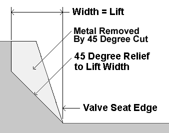
Begin metal removal by cutting the marked area only back at a 45° angle up to the line on the wall (Diagram II·). If the mark is very close to the seat (limited by the edge of bore or head-gasket, etc.), the angle will be greater (more vertical, 60 - 80°). If you cannot be certain of the accuracy of your measurements, use a shallower angle (30°, etc.). Do all the intakes to this stage of completion before continuing. If doing the exhausts also, make these first cuts now.
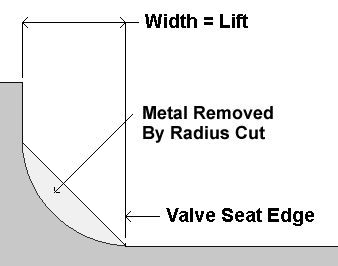
The optional next step is to undercut this angled area to a radius (Diagram III·). The maximum intake radius is the same as the lift; the exhaust radius is 60%. It should curve in and up-hill from the outer edge of the seat to the chamber edge. If the chamber depth is more than the lift, make the height above the lift dimension exactly vertical (90°). If the chamber depth is less than the lift, it will not form a complete 90° ¼-radius.
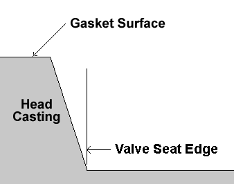
The following 4 diagrams illustrate the modifications as described above. All show the combustion chamber wall facing the left side of the seat. Obviously, this is only true of 8 valves; the other 8 (4 intake and 4 exhaust) face to the right; the correct diagram in these cases is a mirror image.
Chamber Through-Sections |
I· Original Combustion Chamber |
II· Chamber With 45° Relief Cut |
 |
 |
III· Chamber With Radius Cut |
IV· Final Version |
 |
 |
When the reliefs are completed (Diagram IV·), lightly radius the sharp edge where the relief joins the new chamber wall to prevent hot spots, etc. 1/64” radius is enough for intakes, 1/32” for exhausts (higher temperature in this area).
If you wish to “CC” the chambers, do this now. If your calculation results in a smaller chamber volume than you would prefer for compression purposes (ratio is too high), slightly more metal can be removed with relative safety from the exhaust reliefs only, by cutting them back to the left or right edge of the bore or gasket (whichever is closer). There is also a small amount that can be removed from open-chamber heads (340, 906, 452, etc.) by cutting the quench depression (180° location) back to the bore or gasket edge. Don't remove any metal from the quench area of closed-chamber heads (318, 360, 915, etc.). A small additional improvement can be made to the spark plug relief, buy increasing the radius leading from the plug thread into the chamber.
Should you find yourself unable to continue, feel free to E-mail for advice (see the link on the menu below), or you may wish to make a rubbing or impression of your work so far, and submit for my comments; you must enclose a SASE. Remember that the only ways a relief can hurt you are:
» Lack of consistency (the chambers do not match).
» Relief work has damaged the valve seat.
» Chamber volume error results in more than 1/10 point difference in compression between cylinders.
» Relief extends into the gasket surface.
» Extreme roughness (waves, lumps, grinding marks, etc.).
After the work has been completed to your satisfaction, it's advisable to lap the valves in again, to “heal” any light scratches on the seating surfaces and insure proper sealing. Of course, the final step is a thorough cleaning with solvent and air pressure before re-assembly. Remember to blow out all holes, even the ones that were taped, etc.
Bore Relief
In many cases, the valve seat is relatively close to the edge of the bore (e.g., 318 with 340 heads & 2.02” intake valve, 383 with 2.14” intake valve, etc.). The cylinder wall obstructs gas flowing in (or out) of the seat at all points of low to mid-lift. Chrysler factory Max Wedge Super Stock motors with 4.25” bore and 1.88” exhaust valve had the exhaust side of the bore radiused in a funnel shape, and Nascar motors had both intake & exhaust sides radiused. I don't think I'd limit this to heads where the chamber runs outside the bore (where it's necessary, in my opinion). Any chamber where a valve seat is within ¼” of the bore (or less) will flow better if the bore edge is relieved. How far away does the valve have to be before it doesn't matter? I think the full-lift distance is probably zero return, but how much less depends on the port, valve stem angle, dome shape, rod ratio, too many other variables. Be careful not to go too far down the wall into the top ring travel.
A bore edge relief is pretty harmless as to compression loss, it's way under 1 cc.
Note: the instructions given here are based on well-proven, time-tested techniques and are safe & effective for all motors (if carefully applied). I feel that modern air-flow research may be able to make additional improvements on this, but such developmental work is beyond my financial means. In all likelihood, other patterns & theories are effective (to a greater or lesser degree), but the ideas given here are taken from professionally-prepared motors, as well as interpolations from racing drawings & instructions. Your own success depends on the condition of your head castings, and the accuracy of your measurements and work. I cannot be responsible for typographical errors, or improper application of the information given here. Good luck with your project!
|
|


