|
|

|
| ||
|
|
DeSoto Low Deck Strokers (276, 291)
| ||||||||||||||||||||||||||||||||||||||||||||||||||||||||||||||||||||||||||||||||||||||||||||||||||||||||||||||||||||||||||||||||||||||||||||||||||||||||||||||||||||||||||||||||||||||||||||||||||||||||||||||||||||||||||||||||||||||||||||||||||||||||||||||||||||||||||||||||||||||||||


It’s possible to weld and offset grind the rod journal to the increased diameter of the Chevrolet late small block journal (2.100”), using the stronger aftermarket 6.00” rod (Manley, etc.) and bearing, resulting in 3.38125” stroke. The rod and bearing are only very slightly too wide, requiring only minor work.
It’s possible to weld and offset grind the rod journal to the increased diameter of the poly ”A” journal (2.125”), using the stronger & longer 6.123” poly ”A” or ”LA” (340, 360) rod and bearing, resulting in 3.40625” stroke. However, the rod and bearing must be narrowed slightly and precisely from both sides.
Both offset grinding and increased journal diameter can be done together for additional stroke increase; watch the compression distance and overlap.
In addition to the obvious displacement advantage, the raised deck DeSoto motors allow even longer strokes to be used. For example: the stock stroke of the raised deck DeSoto motors is 3.80”. Even with this stroke, the original 6.625” rod length gives a very safe 1.74-1 rod ratio.
Be careful to get a raised deck DeSoto crankshaft, as the main journal bearing size is larger than the low deck at 2.500”. The 276/291 crankshaft will be approximately the same length but is not only much shorter stroke, but the smaller (2.375”) main journals will not fit the raised deck block without extensive modifications.
The original 3.800” crankshaft can be stroked by welding and offset grinding the rod journal, using the original 6.625” rod and bearing. Although I don’t know the practical upper limit, I’m sure that adding .250” is safe; the new stroke is 4.050”, new CD is 1.737”, new rod ratio is 1.63-1.
The stronger 400/430/455 Buick 1967-76 V8 rods are 6.607” long (only .018” shorter than the original), use the same 2.25” rod journal, and width is close enough to work @ .928” (Desoto is .003” wider @ .931”). The pin size is too large @ .997”, and must be bushed down to the DeSoto’s .921” to use OEM-type pistons, or a piston with a larger pin selected. This rod is also available in expensive non-stock lengths for unusual applications.
It may also be possible to weld and offset grind the rod journal to the increased diameter of the Oldsmobile 455 journal (2.500”), using the stronger & longer 6.735” Olds rod and bearing, resulting in 4.050” stroke, CD is 1.62” so the piston is lighter, rod ratio is 1.66-1. The rod and bearing are only .006” narrower, which not cause a problem but measure carefully. Overlap goes up, but so does weight and expensive. This rod is also available in expensive non-stock lengths for unusual applications.
Both offset grinding and increased journal diameter can be done together for additional stroke increase; watch the compression distance, rod length and overlap.
The “Tex Smith” book (among many other sources) says that DeSoto and Dodge raised blocks rods are inter- changeable. This may be true in a practical sense (use one if you can’t get the other), but they are different forgings (the DeSoto is slightly heavier), and two other dimensions are not the same.
DeSoto vs. Dodge Rod Comparison | |||||
Motor | Size | Rod Length | Rod Journal | Piston Pin | Rod Width |
DeSoto | 330, 341, 345 | 6.625” | 2.25” | .921” | .931” |
Dodge | 315, 325 | 6.618” | 2.25” | .921” | .901” |
The length difference (.007”) is probably not important in a hemi. However, the DeSoto rod will not fit the Dodge at all (will have negative side clearance), and the Dodge rod will give excessive side clearance, noise, higher oil consumption and lower oil pressure in the DeSoto.
1952-57 DeSoto Bore & Stroke Data | ||||||
Bore Size |
Bore Size |
3.34375” |
3.500” |
3.59375” |
3.800” |
4.050” |
276 std. |
3.625” |
276.08 |
288.98 |
296.72 |
313.75 |
|
+.030” |
3.655” |
280.67 |
293.78 |
301.65 |
318.96 |
|
+.060” |
3.685” |
285.29 |
298.62 |
306.62 |
324.22 |
|
+.090” |
3.715” |
289.96 |
303.50 |
311.63 |
329.52 | |
291 std. |
3.7200” |
290.74 |
304.32 |
312.47 |
330.41 |
|
+.030 |
3.750” |
295.44 |
309.25 |
317.53 |
335.76 |
|
+.060 |
3.780” |
300.19 |
314.22 |
322.63 |
341.15 |
|
+.090” |
3.810” |
304.97 |
319.23 |
327.78 |
346.59 |
|
330 std. |
3.720” |
290.74 |
304.32 |
312.47 |
330.41 |
|
+.030” |
3.750” |
295.44 |
309.25 |
317.53 |
335.76 |
|
+.060” |
3.780” |
300.19 |
314.22 |
322.63 |
341.15 |
|
+.090” |
3.810” |
304.97 |
319.23 |
327.78 |
346.59 |
|
341 std. |
3.780” |
341.15 |
363.60 | |||
+.030” |
3.810” |
346.59 |
369.39 | |||
+.060” |
3.840” |
352.07 |
375.23 | |||
+.090” |
3.870” |
357.59 |
381.12 | |||
345 std. |
3.800” |
344.77 |
367.45 | |||
+.030” |
3.830” |
350.24 |
373.28 | |||
+.060” |
3.860” |
355.75 |
379.15 | |||
+.090” |
3.890” |
361.30 |
385.07 | |||
Cam
New cams for these motors are not available. However, re-grinds (on your own good used cam) are available from some major cam manufacturers, but few specialize to the point where they can make a specific suggestion (rather than just tell you the specs of what’s available). Chris Neilson is an exception, see Source Table. The array of possible choices is not only frustrating, but the selections are usually based on intended use (RV, street, drags, oval track, fuel, etc.) and not really helpful. Re-ground cams (except welded overlay) have smaller base circles than stock cams, and therefore frequently need longer pushrods, depending on the new lift.
I have a very simple rule for cam selection. It’s based solely on motor size, since many other variables are known and similar: all the original cars are relatively heavy (3500 - 4000 lbs.), have low-number axle ratios, almost all have 2 or 3 speed transmissions (Powerflite or Torqueflite; no 5 speeds or O/D), no EFI, under 400” displacement, with moderate compression ratios, cast-iron heads, restrictive intake manifolds, etc. Forced induction or nitrous cams are special, don’t use these rules.
My cam selection rule does provide a safe choice for a warm street motor, with good manners and acceptable idle, suitable for a stock converter and highway axle ratio, but still provide a nice power increase when the “best” cam is not known, and too many choices are available.
To predict a useful cam for a “warm” street motor:
1. Take the size of the motor when completed. Divide by 10, and round off (330” becomes 33, 276” becomes 28, etc.).
2. Add 180. The result is the cam’s “duration @ .050” lift” (look for it in the cam manufacturer’s specs). For a 330” motor in this case: 213° (330 ÷ 10 = 33; 33 + 180 = 213).
More power? Like that “racy” idle? Afford to lose a bit of low speed power? Add 10 to the .050” duration figure to get a hot motor (for a 330” motor in this case: 223°), best used with high compression (9-1 minimum), 4 bbl. or more, standard transmission or a loose torque converter, dual exhaust and high numerical gears (3.55, not 2.76).
Heavy vehicle? Stock torque converter? 7-1 compression? 2 bbl. carburetor? Subtract 5 from the .050” figure (for a 330” motor in this case: 208°).
3. Advertised (total) duration: use the lowest figure you can find for the .050” duration value predicted in Step 2 above (i.e., 290° advertised duration is preferred to 300°, if both have the same 220° @ .050” lift).
4. Lift: as much as you can get, limited by the choices in Steps 2 & 3.
5. When in doubt, select the smaller of the two choices. More is not better here.
Is this the “very best” cam? No, but unless you ask an expert who has successfully built motors very similar to yours, it’s better than guessing, and will provide satisfying results. It will not be the “optimum” cam, which will require extensive testing and dynamometer work.
Don’t be too aggressive with motors under 300”, or under 8-1 compression; too much cam will make them hard to drive.
If the cam manufacturer suggests a specific valve spring, use it, don’t be creative. The motor will not last longer with weak springs, or develop more power with stronger springs.
Heads
Compression
The best available information suggests that the heads can be safely milled at least .030" for more compression by removing material from the head gasket surface. There is no accurate formula for determining how much the chamber volume is reduced by each .010" (the common distance for comparison) taken off the gasket surface, but a good prediction for a mild cut can be made by measuring the chamber diameter in the head (not the bore). Take the resulting figure, and use this formula:
For example, if a chamber measures 3.85”, 3.85 squared = 14.82. 14.82 × .7854 = 11.64. 11.64 × .010 cut = .116” removed from the chamber. If the compression ratio was 9.0-1, the original chamber volume is calculated as follows:
So for this 318 the chamber volume is calculated: 39.74” ÷ 8 = 4.968”. Removing .116” with the .010” mill reduces the chamber to 4.852”. The new compression ratio (if no other changes to the piston or head are made) is calculated as follows:
The safe upper limit for milling the head gasket surface is not known, but it is probably .090” or less from the standpoint of structure, leaks, rigidity, etc.
If the heads are milled for compression, the head's intake port surface must also be milled; the formula for how much to remove is based on the intake port angle, which differs among the engine families. Another factor is the point where the intake port surface cut is so deep that the cutter removes material from the valve cover rail, bolt perches, etc. I strongly suggest that you closely examine the intake port surface before beginning any milling operations.
The amount to be removed from the intake port surface will always be more than the amount removed from the head gasket surface. This is not true for all motors, but hemi motors have intake ports farther from vertical than the cylinder bank axis. As an alternative, the manifold's intake port flanges can be milled, but this creates a situation where this manifold will only fit this motor, the manifold can't be used anywhere else, and any subsequent manifold choice must also be milled. Milling the head's intake port surface is the practical choice. To determine how much to remove from the intake surface:
Porting is best left to professionals with experience with these motors (or a flow bench), but the “bowl” area immediately below the valve seat is generally not fully finished, and contains casting irregularities and a certain degree of mis-match between the machined valve seat and the cast upper port area. Enlarging the bowl to match the seat ID, and carefully blending the bowl into the port is recommended.
Matching the intake ports to a good quality gasket is also recommended. A 6” carbide bit will allow the slightly enlargement to be blended into the port. Don’t go beyond the gasket outline.
The exhaust ports can also be gasket-matched, but it’s important to leave the port openings smaller than the exhaust manifold or header flange opening.
If the rocker stand, water jacket, accessory bracket, spark plug and valve cover bolt holes, etc. are plugged or masked, clean-up will be easier. Also mask the exhaust seat, port and guide holes if only modifying the intake side.
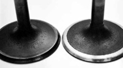
The intake valve is large typically large enough, but a slightly larger valve will help (1.94”, etc.). Don’t plan too big a size, or the outer edge will overhang the gasket. The bowl area should be enlarged in proportion. The valve’s head shape can be improved by narrowing the seat face to .080” wide with a back-cut at a very shallow angle, as small as 7° (shown below, left). This cut should just touch the stem-to-head radius, and remove the greatest amount of metal from the back of the valve head. This reduces weight, and improves flow. Grind off any raised numbers or marks on top of the valve. The shape should resemble the “tulip” shape on the right valve in the picture (below, right), rather than the left “nail head”. The outside edge where the face joins the margin (at the top of the valve, chamber side, not visible in picture) should be left at a sharp 90° angle, with a 1/64” maximum radius or bevel; just “break” the edge. Polish the top.
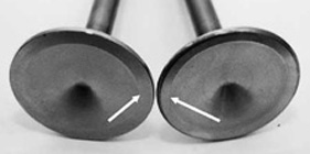
A slight oversize exhaust valve can easily be adapted from another motor. The bowl area should be enlarged in proportion. Remember that the stem diameter must match, and the length must be the same or very slightly longer. The valve’s head shape can be improved by narrowing the seat face to .080” wide with a back-cut at a very shallow angle, as small as 11° (shown below, left). This cut should just touch the stem-to-head radius, and remove the greatest amount of metal from the back of the valve head. This reduces weight, and improves flow. Grind off any raised numbers or marks on top of the valve. The shape should resemble the “tulip” shape on the right , rather than the left “nail head” valve in the picture (below, right).
The outside edge of the face at the corner of the valve (opposite the seat) should be back-cut 25° & radiused a bit (1/16”-3/32”) to make a smooth curve from the margin (straight area) to the top of the valve (shown below, right). A high polish on the top will slightly reduce heat absorption.
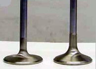
Valve Head Re-Contouring Modifications | ||
Shallow Back Cut to Seat |
Exhaust Margin Radius |
Nail Head vs. Tulip Head |
 |  |  |
For some motors, an adapter allows use of the Chevrolet aluminum water pump, see the Source Table. This is a nice weight saving, and the Chevrolet pumps are easily available and less expensive.
If your car runs hot above 30 mph, it’s the water circulation, not the fan. No fan helps at this speed, in fact, you don’t need a fan at all.
The best thermostat temperature for performance is 160°. Although this is not the best for cold-climate comfort or gas mileage (195° is better here), it reduces the intake manifold temperature and prevents the incoming mixture from pickup up heat from the manifold. The motor may also tolerate slightly more ignition advance, but not leaner mixture.
Use a 13 or 15 lb. minimum pressure cap, and no more antifreeze than you need (less is better, but not none as it also lubricates the water pump).
Cars operated in warm climates can block off the exhaust cross-over with a blank intake manifold gasket, etc.
Cold air to the air cleaner also produces extra power. A cold air system can be retro-fitted to most cars without permanent modification to the car or original air cleaner. All modern air cleaners have the same 5-1/8” opening for the carburetor, so the brand etc. doesn’t matter. Some need dents and notches to clear your choke, linkage, etc. so try before you buy.
The total throttle plate area of a large 4 bbl. carburetor is about equal to a single 3½” ID opening. Many cars have lightening holes in the radiator bulkhead large enough to permit a 3½” round flanged sheet metal duct to catch cold air before it hits the radiator. However, most air cleaner cans aren’t tall enough for a 3½” hose to enter the side, so some fabrication is needed. Get an A/C sheet metal duct with a rectangular shape at one end and round at the other. A rectangle 5” × 2” or 4” × 2½” is about the same area as 3½” hose. Trim the rectangular end to match the curved side of the air cleaner. Cut out the side with a drill & snips large enough for the duct to go through the side (not stop outside). Insert in from inside until the flange is flush with the inside wall. Gasket and pop-rivet the rectangle to the wall of the can, and slip the hose on the other end. Connect the air cleaner to the duct with dryer hose, finish with hose clamps.
See the “Tex Smith” book or the Source Table for adapting an “LA” pump, improving oil flow to the bearings, converting to “full-flow” oil filters, converting to spin-on cartridges, etc.
If you wish to use synthetic oil, I suggest not changing over until the rings have broken in, about 1,000 miles should be enough.
The maximum oil pressure setting is controlled by the pressure bypass spring in the pump. Raising the maximum pressure can be done by shimming the existing spring (be careful), using a heavier spring, or higher oil viscosity. Only thicker oil will affect pressure at lower speeds. The general rule applies: 10 lbs. of oil pressure for every 1,000 RPM is sufficient even for high-performance use. 6,000 RPM requires 60 lbs., no more. Higher pressure simply wastes power, and puts additional stress on the drive gears.
Oil delivered to the valve gear drains back into the oil pan through fairly small holes, located on the lower (exhaust) side of the head. It’s important that these holes be clear of any debris, sludge, etc. I prefer to enlarge the holes, and then radius the upper ends of the holes with a counter-sink forming a small funnel to improve drain-back.
Although cars were not equipped with PCV (“positive crankcase ventilation”) valves until 1964, I suggest using them whenever possible. However: the PCV is (normally) connected directly to the intake manifold or carburetor base flange, and therefore affects intake manifold vacuum at all times. The valve’s function is determined by three main factors:
1. high vacuum orifice size
2. low vacuum orifice size
3. restrictor cone spring tension
During idle, deceleration and light throttle cruising, a tapered cone inside the valve is held against the small orifice by engine vacuum, leaving only a small opening for crankcase vapor to be drawn into the motor. The small aperture size is a function of engine size and idle vacuum. This has minimal effect on idle mixture, but it will speed up the motor slightly and (probably) lean it out somewhat. A motor with a big cam should use a PCV with low spring tension so that the cone is fully retracted at idle. - this is what balances the big orifice against high vacuum, pulls the cone back and opens the big orifice when vacuum drops.
During open throttle conditions, the spring tension overcomes the lower vacuum and pulls the cone away from the small opening, and allows crankcase vapor to be drawn into the motor through the larger aperture. This larger size is a function of engine size; my guess is that any V8 size is acceptable here.
Remember that the PVC must draw from a crankcase source, usually a valve cover. An adapter or hose extension may help to use an existing fitting. In some cases, the existing road draft tube (the predecessor of the PCV) will accept a PCV with a minor modification. The rubber grommet from a small block passenger’s side valve cover can serve as an adapter. Insert into the road draft tube opening in the valley cover, then insert the PCV valve.
Ideally, a late Chrysler oil-separator type breather should be installed in a valve cover to prevent oil droplets from entering the hose. The other valve cover (or valley cover) should have a filtered air inlet or a line leading to the interior of the air filter canister, so clean air continuously circulates through the motor.
(Click here for the next page)

See these Victory Library booklets | |||||||||||||


