|
|
 |
Here I will make various observations and comments on how the chassis and suspension of Chrysler and other unibody (frameless) automobiles including Camaro, Chevy II, Mustang, &c. can be improved. New material will be added regularly, and eventually better organized. Click below to jump directly to an individual topic. |
“Tall-boy” frame connectors
The function of the non-existent frame beneath the doors on unibody cars is assumed by the folded sheet metal of the floor, rocker boxes and other light-gauge shapes. While sufficient for mild use, this design does not provide sufficient rigidity to prevent the body from skewing and unloading a wheel, &c. The floor in this area is almost flat, and offers little resistance to warping (force applied to one corner twists the floor into a 3-dimensional shape). The driveshaft tunnel is very helpful in preventing bowing in the center, but its location prevents it from resisting twist applied through an outer corner.
Replacement of the existing structure with an actual frame or sub-frame is not practical due to the complexity of the design. |
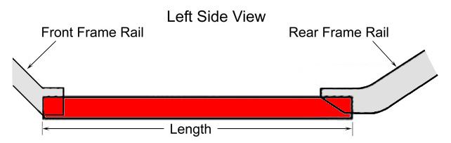
Commercially available “frame connectors”, as shown right (click the image for a larger view) are a partial cure, fairly inexpensive and relatively simple to install but limited by the necessity of remaining outside the passenger compartment. Except for floor cuts in some |
|
|
cases, the frame connector is simply a length of rectangular steel box tubing, usually 2” to 3” tall by 1” to 1½” wide, welded or bolted flush with the bottom of the existing rocker and floor, and to the existing sub-frames front & rear as a stiffener. While this is a major improvement, there is a limit to its effectiveness: the height of the connector, which is the 3rd dimension. Note that in this diagram the connector height is limited by the floor, and less then the height of the existing sub-frames. The usefulness of the connector is a function of stiffness (resistance to change in shape), as opposed to strength (resistance to breakage), and this is greatly affected by its height. There is no simple way to hide extra height; 3” is about the point where ground clearance is reduced, and the modification becomes visible. Increasing the width or gauge (wall) thickness has very little effect once the thickness exceeds the original sub-frame.
There is a method of greatly increasing the effectiveness of a connector without making it cosmetically unpleasant, although it must be fabricated and requires complex installation. This will increase the stiffness of any unibody chassis, even one already equipped with a roll cage (although obviously a smaller improvement). |
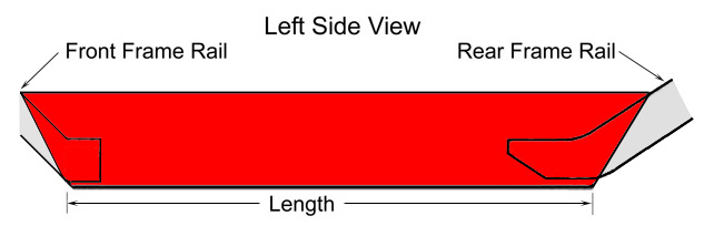
The concept is very simple: the “Tall-boy” connector extends up through the top of the rocker box and into the area now occupied by the lower door body. Its greater height increases stiffness by easily 100% with only a minor weight penalty. Click the image for a larger view.
|
|
|
The connector’s height need not exceed the existing sub-frame height. The maximum and largest practical sizes will depend on the structure of the individual car, the design skill of the fabricator, the need for added stiffness, &c.
In some cases, the connector height must be limited to retain the window crank mechanism, door lock, &c. I suggest removing the inner door panel for inspection to determine the position of these components, and compare this to your service manual before making any plans. The matching area inside the front & rear of the existing door outline (where the door hinges, seals, and locks are located) of course must also be cut out, although this work will be invisible. Removal of the front fender will make this work easier.
The connector should be welded to the door outline for best effect, so this cut-out area should match the cross-section of the connector closely. If the hole is made too large, a simple flat plate should be overlaid and welded first to the connector, and then the door outline. Rather than make a rectangular hole in a large plate, the plate can be split in half to make fabrication easier.
It’s important to recognize that the new door sill (step-over) height should be as great as your comfort and fabrication skills permit. This may meet a natural obstruction inside the fender, &c. In some cases a section can be notched out of the connector’s top, side or both to permit easier attachment. Where the notch is not filled with or attached to existing structure the opening should be boxed in. The connector length is not absolute, but should overlap (rather than merely intersect) the existing sub-frames for maximum effect.
Rather than limit the connector length to join the existing sub-frames, every effort should be made to attach the rear of the connector directly to the forward end of the rear spring support structure (spring hangar box, trailing arm pivot, &c.). The forward end of the connector should approach the lower control arm mount as closely as possible. If the connector is outboard of these areas, it can be cut and angled, or doubled with an extra section added to the inner surface to align. These points insure that load applied to the wheel is not resisted only by the local structure, but by the entire chassis. The connectors need not be parallel to each other (as seen from above in plan view) since the width across the control arm mounts is narrower than the width across the rear spring mounts in most cases, but the body shapes that the connectors must transect are relatively parallel, which will limit the alignment.
The connector need not be a single piece such as 2” by 8” (although this shape is commercially available in 16 gauge steel), but may be made of multiple rectangles stacked vertically (two 2” by 4”), or a box made by connecting two rectangles vertically with plates (two 2” by 2” boxed on each side with 8” plate), or entirely fabricated (two 2” open channels facing each other boxed on each side with 8” plate).
The choice of wall thickness should be between the thickness of the existing structural shapes as a minimum, but perhaps no greater than .083” unless the maximum height is very limited. Greater depth (top to bottom) is by far the best use of metal rather than thickness or width. |
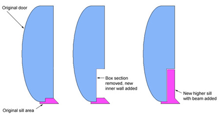
However, this poses an obvious question: what happens to the door that used to occupy the space now containing the upper half of the connector?
The outer door skin remains visibly untouched. It will require no modification, but wet rags &c. should be used to protect the paint from welding heat.
After careful measurement, the front & rear sides and |
|
|
bottom of the door shell have a thin “U”-shaped section the width of the connector plus a small safety margin (I suggest between 1/8” and 3/8”) neatly removed with a Sawz-All &c. E.g., if the connector is 2” wide, the cut should be at least 2-1/8” up to 2-3/8” wide.
The lower inner door shell is separated from the door body by a cut across front to rear slightly above the connector height, then moved deeper into the door body by the connector width and re-attached.
When the door is closed, the connector fills only the cut-out space and is completely invisible from the exterior. The modification canot be detected from outside.
The door weighs slightly less than the original, and the connector only adds a few pounds.
The connector height above the previous rocker will increase the “step-over” height in the same way as in a Jaguar XK-E, &c. However, this is much less intrusive than a door bar or diagonal from a roll bar. For best cosmetic effect, the door panel may be split horizontally and re-used, with the upper half attached to the original door and the lower half or a section of matching carpet attached to the inner surface of the connector. Th original sill cover plate may be modified to add a nice touch. A section of the door seal can be applied to the bottom of the cut-out if you wish.
Continuously welded seams are not absolutely necessary as long as complete penetration occurs, but will help keep the interior dry. I suggest adding drain holes at the lowest points to prevent rust.
The new sill should be caulked to the floor.
Caution: this is a major project, not done in a week-end. It will be very difficult and expensive to restore the car afterwards. Measure twice, cut once. |
|