|
|
 |
When a V8 head is milled for gasket surface repair or compression increase, the new (lower) position on the cylinder bank moves the intake port surface closer (laterally) to the center of the motor and to the opposite head’s ports. Metal must be removed from either the head or the intake manifold face to “shrink” the port-to-port distance so the manifold will fit and seal properly (other surfaces such as valley cover, end seals, etc. may also have be compensated for). If this is not done, the intake manifold cannot be installed. The following analysis, diagram and calculations are through the courtesy of Michael Doty.
The formula for how much to remove is based on the intake port angle, which differs among engines. The amount to be removed from the intake port surface may be more or less than the amount removed from the head gasket surface. As an alternative, the manifold’s intake port flanges can be milled, but this creates a situation where this manifold will only fit the subject motor, the manifold can’t be used anywhere else, and any subsequent manifold choice for the subject motor must also be milled. Milling the head’s intake port surface is the practical choice. How to calculate the intake surface mill distance, based on the intake port face angle, is described here: |
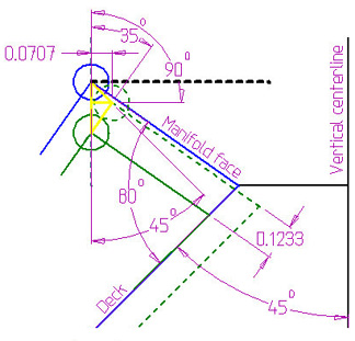
In this diagram (shown right, click it for a larger version on a separate page), the left point of the heavy black dashed line will represent a reference point on the face of the intake manifold, it could be the intersection of a bolt hole center and the gasket surface. The head’s manifold face is an 80º included angle to the deck. In essence, the distance of the bolt holes between the opposite heads needs to be maintained. It doesnt matter if the bolt holes are angled in relation to the gasket surface. | |
|
The yellow lines connect the three points of where the reference point was to begin with, where it moves after milling the deck .100", and where the reference point needs to be moved to in order to intersect a vertical line from the original point. The triangle is split into two right angle triangles.
In this example, the solid blue line represents the original head position, and the circle merely outlines as the reference point on the head’s manifold face, such as the bolt hole center. The green dashed line is the position of the head if it was moved (milled .100) at a 45º angle. The green dashed circle is where the reference point is now, before milling the manifold face. The reference point has moved toward the center of the engine .0707 (SIN - the “sine” trigonometric function - of 45º × .1) on each side. The 45º angle is in reference to the vertical line drawn through the original reference point.
To make the manifold fit again, our reference point needs to be moved back towards the outside (solid green line) to where it will intersect the vertical reference line, or .0707 in this example. Since we are now working with the manifold face angle, we have to divide .0707 by the SIN of 35º, which is 0.5736 (rounded off) (.0707 ÷ 0.5736 = 0.1232). To sum up the math into a single calculation: |
Intake Surface Mill Proportion = .707 ÷ (SIN (45 - intake face angle)) |
Where the face angle rakes back (more than 45 from vertical when assembled on the motor), the angle is positive, such as Chrysler RB, SBC, etc.
Where the face angle rakes in (less than 45 from vertical when assembled on the motor), the angle is negative, such as Chrysler LA, etc. Remember: subtracting a negative number makes it a positive number!
Multiply the result of the calculation by the head gasket mill distance to get the amount to be taken off the intake flange surface for proper manifold alignment. In some motors (especially those with integral valley covers), additional compensation must be made for end seals, etc.
A positive example: RB (413, 440) face angle is 10° positive.
.707 ÷ SIN(35) = .707 ÷ .5736 = 1.2326, so remove .0123” for each .010”.
A negative example: LA (340, 360) face angle is 3° negative.
.707 ÷ SIN(48) = .707 ÷ .7431 = .9514, so remove .0095” for each .010”.
Here are some common motors with the math already done. |
Common V8 intake face angles & mill cuts, per .010” removed from head surface |
Mfg. | Motor | Size | Face Angle | Intake Cut |
Chevrolet | SB 1955-* | 265, 283, 302, 327, 350, 400 | 10° | .0123” |
Chrysler | “LA” 1964-* | 273, 318, 340, 360 | -3° | .0095” |
“B/RB” 1958-78 | 350, 361, 383, 400, 413, 426W, 440 | 10° | .0123” |
Mopar hemi 1964-71 | 426 | -13° | .0085” |
Chrysler hemi 1951-58 | 331, 354, 392 | 25° | .0207” |
DeSoto hemi 1952-57 | 276, 291, 330, 341, 345 |
Dodge hemi & poly 1953-58 | 241, 259, 270, 315, 325 |
Poly “A” 1956-67 | 277, 301, 303, 318, 326 | 10° | .0123” |
Ford | SB 1962-* | 221, 260, 289, 302, 351, 400 | 0° | .0100” |
FE BB 1958-* | 332, 352, 390, 406, 410, 427, 428 |
385 FF BB 1968-* | 370, 385, 429, 460 |
Oldsmobile | 1949-63 “Rocket” | 303, 324, 371, 394 | 20° | .0167” |
1964-* (late) | 330, 350, 400, 403, 425, 455 | 0° | .0100” |
Pontiac | 1955-* | 265, 287, 301, 316, 347, 326, 350, 370, 389, 400, 421, 428, 455 | 0° | .0100” |
See these other Victory Library booklets |

| 
| 
| 
| 
| 
| 
|

| 
|

| 
|

|

|

|
|