|
|
Purpose:
All modern automotive engines use an intake manifold
to connect the fuel/air management device to the intake ports in the head(s) of the motor. This device may be carburetor(s) or injection, using throttle disc(s) or slide(s) to regulate the air supply to the motor. “Manifold” means “common” or “shared” -
the same word is used to describe hydraulic & pneumatic connections.
There are many misconceptions and false generalizations about how manifolds work, and how the different types function. My purpose here is to explain some of the factors in manifold design and operation, and to evaluate these
factors when selecting or modifying your intake system. |
Manifold Designs:
There are several different intake manifold types in common use. Click on the name of a specific type to jump to that topic, or just continue reading down the page. |
|
The following Chart shows features characteristic to each manifold Type. Relative efficiency is based on best design of each type. Motor: V8 with single 4 bbl. carburetor (except Type 3 and as noted). |
Manifold type |
Description |
Carb. capacity
available to 1 cyl. |
Throttle response
& mixture velocity |
Idle
quality |
Mixture
dist. |
Max power
potential |
Type 1-S |
Single-plane |
100% |
Fair |
Fair |
Excellent |
Excellent |
Type 1-S(p) |
Single-plane with plate |
60 - 90% |
Fair |
Good |
Excellent |
Very good |
Type 1-S(d) |
Divided single-plane |
50% |
Fair |
Good |
Fair |
Good |
Type 1-T |
Tunnel-ram |
100% |
Worst |
Worst |
Excellent |
Best |
Type 1-C |
Cross-ram |
100% |
Worst |
Worst |
Excellent |
Excellent |
Type 2 |
Dual-plane |
50% |
Excellent |
Excellent |
Very good |
Good |
Type 3 |
Isolated runner |
1 bbl. only |
Best |
Best |
Best |
Excellent |
Carburetor Size:
The capacity of a 4 bbl. carburetor is rated in CFM (“cubic feet per minute”: how much air volume will pass through the carburetor in one minute under test conditions) at 1.5” Hg (vacuum, given in inches of mercury). 2 bbl. carburetors are usually rated at CFM at 3” Hg. Only an engine with that exact vacuum reading at full throttle will receive that exact CFM. If the carburetor is substantially smaller than the recommended size for the motor, the manifold vacuum at WOT (wide open throttle) will be higher than 1.5”, and the CFM will increase. This explains why the power loss due to an undersized carburetor may not be too severe - the motor’s higher vacuum “forces” the carburetor to deliver more flow. If the motor is too small (or carburetor too large) the reverse occurs: the vacuum @ WOT falls below 1.5” hg, and the CFM is reduced. The formula for the actual flow at vacuum levels other than 1.5” hg is: |
Actual CFM = |
Original Rated CFM |
(Rated Vacuum ÷ Actual Vacuum) .5 |
To use the formula, you must know the actual vacuum present @ WOT. This may be determined with an in-car vacuum gauge by a brief full-throttle run in high gear from low speed. Divide 1.5 by this figure, then take the square root of the result. Divide this into the original (mfg.’s rated) CFM to get the actual flow. |
To compare the CFM capacity of a 2 bbl. (such as Holley 500, or 6 Pack carburetors) to a 4 bbl. (such as Holley 3310 750), multiply the 2 bbl. rating by .707 (or 70.7%). For example: 6 Pack total CFM rating = 1350. Converted to 1.5” Hg rating for comparison to 4 bbl.: 1350 × .707 = 954 CFM.
If the engine is too small to pull 1.5” of vacuum at WOT, the carburetor flows less. Dropping down to 1” vacuum (the carburetor is larger than predicted by formula) will reduce flow to about 82% of rated CFM (a 600 flows 490) and improve power a bit (+1.7%) but make your fuel curve slightly weird.
If the engine is small enough that vacuum drops to .5” the signal becomes too weak to meter effectively. This is an advantage for FI because there is no minimum vacuum needed.
If the engine is large enough to pull more than 1.5” (the carburetor is smaller than predicted by formula), maximum power is reduced (compared to enough carburetor to run at 1.5”).
For example if it’s 3” maximum power is down about 5.2%, and the carburetor flows more than the rated CFM by about 41% (a 600 flows 848).
As the engine gets larger eventually WOT vacuum is so high that some unwanted function kicks in (metering rod, power valve, secondary air valve etc.), or air through the venturi goes sonic.
Even this method is not practical for carburetor selection based solely on flow capacity, as the CFM rating is for constant flow on a test bench. While the motor is running, the vacuum in each individual manifold runner obviously rises and falls as that cylinder goes through its cycles, but that same intermittent vacuum is also partially present at the carburetor - flow through a carburetor is never constant. The intake vacuum cycles do not overlap completely, even with 8 cylinders, even at 10,000 RPM.
|
CFM Size Calculation By Formula:
Many sources, including Holley, have suggested that carburetor capacity for a given engine size, RPM, and VE (volumetric efficiency) can be predicted by the following formula: |
CFM = Engine Size × RPM @ Peak Power × VE ÷ 3456 | However, this “formula” predicts the following: |
Motor | Size | Carburetor CFM | VE | RPM |
6-Pack | 440 | 1350 (954 actual) | 100 % | 7,500 |
85 % | 8,800 |
Chevrolet Z-28 | 302 | 780 | 100 % | 8,900 |
85 % | 10,500 |
Pro Stock | 500 | 2400 (2 1200 CFM Dominators) | 100 % | 16,600 |
As you will note from these observations, and the results from the Table (especially the completely unrealistic RPM levels), the selection of a carburetor for a specific installation is not an absolute function of engine size in cubic inches vs. carburetor size in CFM. A carburetor of a given size can supply motors of very different sizes depending on several factors:
» Intake manifold characteristics (dual-plane must be larger than single-plane, large plenum allows smaller carburetor, etc.)
» Number of cylinders (for the same size motor, 6 cylinders require a larger carburetor than 8 cylinders)
» Minimum vacuum necessary for intended use (as low as .5” hg @ WOT for maximum performance, or much higher vacuum for best mileage and response)
» Internal design features of the motor (volumetric efficiency, cam timing, rod to stroke ratio, port volume, etc.)
A carburetor of only 500 CFM capacity can supply a 400 HP motor quite efficiently with a single-plane manifold with a large plenum volume. |
A 600 CFM carburetor will work acceptably on a 273” motor with a dual-plane manifold with a small plenum volume, especially with a short-duration cam to provide a strong vacuum signal. |
In summation, don’t rely on a formula to determine your carburetor choice - it’s only by accident that they’re not too far off. It’s far safer and more practical to use what has worked well on another similar engine. Remember to take into account the vehicle weight, gearing, stall speed, how strong a vacuum signal your cam will generate, the characteristics of your manifold, and whether it offers easy after-installation modifications, such as Type 1-S(p).
|
Cylinder Grouping:
In most Mopar engines (exceptions: early hemi 1951-58, late hemi 1964-*, all poly 1955-66) intake ports are placed in pairs: 1 & 3, then 5 & 7 from front to rear on the driver’s side, and 2 & 4, then 6 & 8 on the passenger’s side. If we wish to split them into 2 groups, the obvious method is to make “left bank” and “right bank” categories: Left = 1, 3, 5 & 7, and Right = 2, 4, 6 & 8 (as is done in the case of Type IIb manifolds, as I will explore later). However, this has certain disadvantages, which become apparent when the exact “timing” of cylinders is explored - in what order do they draw gas from the manifold.
|
Firing Order:
The typical firing order for a V8, which determines the sequence of intake strokes, is shown here. I have used red & green to indicate alternate-firing cylinders from this point on - please note that cylinder grouping for some manifold types will include cylinders with sequential firing order, and some mixture disruption will occur. |
| 1 - 8 - 4 - 3 - 6 - 5 - 7 - 2 |
Now some additional comments about each Type:
|
Type 1-S:
The Single-Plane
This manifold type is typically a lighter and simpler casting, but frequently made taller for the following reasons:
» Slightly increases runner length
» Gives the best alignment of the runners with the roofs of the intake ports (typically the most active & useful area)
» Adds plenum volume for more peak power
» Added volume also buffers (damps) reversion pulses, helps prevent disturbance of flow to other runners
» Slows the mixture down as it leaves the carburetor, allowing an easier turn into the runners, and insuring minimal fuel separation and fallout of un-vaporized fuel droplets
Each runner can also be accurately “aimed” laterally and vertically at the port.
All cylinders can draw simultaneously from the carburetor - there is no separation. This means each cylinder in turn “see” the entire carburetor capacity. The downside is that the vacuum signal is weakened not only by reaching all 4 bbls. (instead of only 2, as in a dual-plane manifold), but the plenum volume may be double that of a dual-plane, damping out the signal. This typically requires richer jetting all around, an a bigger pump shot.
Plenum volume can be added with a spacer plate between the carburetor and manifold. This increases the “sharing” effect slightly, but may also improve distribution by allowing mixture leaving the carburetor to slow down slightly as it makes the turn into the runner. Reduces speed makes the paths of the air and fuel droplets more similar - if the speed is too great, the air makes the turn, but the larger droplets don’t. It does not help atomization, but at least all cylinders receive the same proportion.
The opposite modification (reducing plenum volume) is typically dealt with by adding metal (or other gas-safe material) to the floor of the plenum, in various shapes (called “turtles”) which also re-direct mixture between runners. Plenum reduction can also be done as shown in Type 1-S(p) (below). |
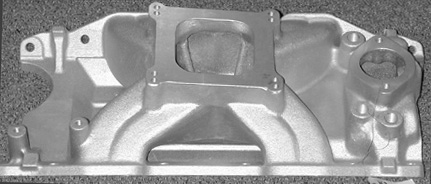
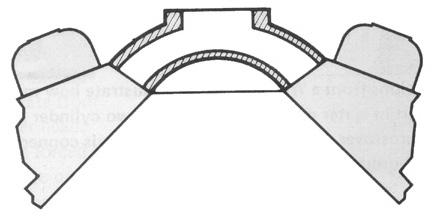
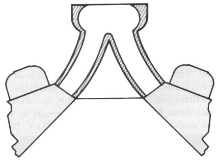
Single-Plane Manifold |
Holley Strip Dominator for LA W2 |
Generic Cross-Sectional View |
 |
 |
Type 1-S(p):
The Single-Plane with Divider Plate is typically an after-purchase modification of a Type I. This is basically a hi-tech version of the Type 1-S(d): Divided Single-Plane (see below), except that left to right separation is less than complete, and adjustable. The purpose is to improve throttle response by reducing the plenum volume, so that the buffer effect is less when a vacuum signal reaches the plenum. It may also be helpful in correcting left to right mixture distribution problems, especially in oval-track motors running alcohol.
A metal plate is added, usually by inserting or suspending it from the carburetor flange so that it partially separates the plenum left & right. The degree of separation depends on the percentage of the plenum masked by the plate (front to back), and how closely-fitting the plate is to the floor of the plenum. This makes for relatively-easy “on the spot” tuning for track conditions, if several plates are prepared in advance. Tuning can be done by substituting a larger or smaller plate, or (possibly, not known) by drilling holes through the separation area. As a thought (not tested): front to rear mixture distribution problems could potentially be dealt with by drilled a large hole closest to the richer cylinders, weakening the signal locally.
This method supplies the cylinders as if it were 2 separate in-line 4 cylinder engines. |
| Here are the intake ports, grouped based on which side of the carburetor they are supplied by, and in firing order: |
Left Side of Carburetor
1 - 3 - 5 - 7 |
Right Side of Carburetor
8 - 4 - 6 - 2 |
This manifold is basically a Type I as to original construction. The modifications are entirely internal and usually invisible, unless the plate has been attached to a spacer. |
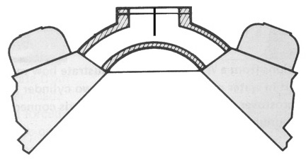
Single-Plane Manifold with Divider Plate - Cross-Sectional View |
 |
Type 1-S(d):
The Divided Single-Plane has been Chrysler factory installed on some 273 & 318 LA motors, and most 1957 Fury polyspheric A, 1955-58 Dodge D500, DeSoto Adventurer & Chrysler 300 early hemi, 1958-62 B, and 1959 & 1962-64 Chrysler 300 RB dual-quad motors. The manifold is divided left and right immediately under the carburetor (except for a small notch for idle balance); it’s basically a low-tech version of the Type 1-S(p): Single-Plane with Divider Plate, except there is almost complete left to right separation. Each side of the manifold is fed by 1 primary and 1 secondary barrel. The cylinders are sorted into 2 groups: left and right banks. Both of each adjoining cylinder pair (1 & 3, 7 & 5; and 4 & 2, 6 & 8) are fed from 1 side of the carburetor. As you can see, 5 & 7 represents sequentially-firing cylinders, so mixture distribution between this pair will suffer.
The individual runners are typically very short, and allow only minimal separation of mixture flow between each one of an adjoining pair of intake ports, so they are sensitive to high-overlap cams.
This method supplies the cylinders as if it were 2 separate in-line 4 cylinder engines. |
“Log” manifolds are common to in-line 4 & 6 cylinder motors, where they function as single-plane types. However, some of the earliest V8 performance intake manifolds were made by treating each cylinder bank as a separate motor, like 1-piece divided single-plane castings. The manifold consists of 2 separate castings with no balance or connecting passage. Each mounted 2, 3 or 4 carburetors (usually 2 bbl. Stromberg 48 or 97; later Rochester 2G were used), and is bolted directly to 1 cylinder bank. The castings resemble simple pipes, are completely hollow internally, with no dividers or separation. The only purpose is more power - idle quality, mixture distribution, throttle response, etc. are all crude. Some were sold as a kit of parts to be assembled & welded by the user (the Crower “U-Fab”).
These manifolds are only curiousities now, but were “king of the hill” back in the early to late 1950s, and held Top Fuel records on the early Swamp Rats. |
| Here are the intake ports, grouped based on which side of the carburetor they are supplied by, and in firing order: |
Left Side of Carburetor
1 - 3 - 5 - 7 |
Right Side of Carburetor
8 - 4 - 6 - 2 |
|
This manifold type is typically a lower, lighter, and simpler casting, cheaper to make, and giving better hood clearance, as the runners leading from the carburetor to the intake ports are all at the same height. |
Divided Single-Plane Manifold - Cross-Sectional View |
 |
|
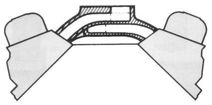
Type 1-T:
The Tunnel-Ram is a variation of the Single Plane. To use wave reflection to increase volumetric efficiency at a practical engine speed, a runner length greater than the distance from the intake port to the plenum is needed. This is accomplished by extending the runners vertically, typically to 8-12” long. This also places the plenum above the valley area, increasing internal volume. The carburetor(s) are still generally in-line with the crank-shaft axis (front to rear), if more than 1 is used. This method supplies the cylinders as if it were 2 separate V4 cylinder engines, placed 1 behind the other. |
| Assuming 2 carburetors are used, here are the intake ports, grouped based on which carburetor they are supplied by, and in firing order: |
Front Carburetor
1 - 4 - 3 - 2 |
Rear Carburetor
8 - 6 - 5 - 7 |
Some degree of separation between the front (#1, 2, 3 & 4) and rear (#5, 6, 7 & 8) cylinder groups occurs, due to the relatively small area of the plenum between the 2 carburetor mounting points.
Interchangeable plenum tops using 1, 2, 3 or 4 carburetors are also found in these models. |
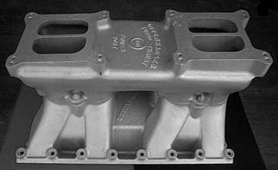
Tunnel-Ram Manifold |
Offenhauser 426 Hemi |
Generic Cross-Sectional View |
 |
 |
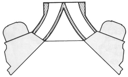
Type 1-C:
The Cross-Ram is another variation of the Single Plane, except that it uses runners even longer than the Tunnel-ram, typically to lower the acoustically-tuned peak torque RPM. This is done by moving the carburetors diagonally away from each other, so that the runner length is increased to about 12-15” or more. This places the plenum above the entire valley area, and increases internal volume. In extreme cases (1960 Chrysler 300F) the runner length of 30” places each carburetor above the valve cover of the opposite cylinder bank. This maximizes torque at 2800 rpm to help accelerate these heavy vehicles. This method supplies the cylinders as if it were 2 separate in-line 4 cylinder engines. |
| Assuming 2 carburetors are used, here are the intake ports, grouped based on which carburetor they are supplied by, and in firing order: |
Left Carburetor
8
-
4
-
6
-
2 |
Right Carburetor
1 - 3 - 5 - 7 | |
Considerable separation between the left (#1, 3, 5 & 7) and right (#2, 4, 6 & 8) cylinders occurs, due to the relatively small area of the plenum between the 2 carburetor mounting points. The “long ram” factory manifolds only had a balance passage for idle quality (missing in the photograph below - normally a hose connecting the 2 stubs extending from the carburetor bases), with almost no “sharing” between left and right. Short rams (12-15” runners) may have the size of the connecting passage (or “window”) increased for more peak power, or nearly shut off for better idle quality.
Some models have interchangeable plenum tops using 1, 2, 3 or 4 carburetors.
Click on 1 of the pictures in the Table below to see a full-size picture of the manifold on a new page: |
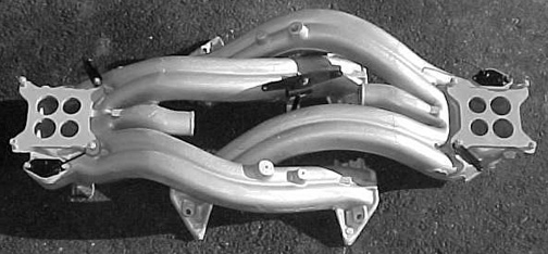
Cross-Ram Manifolds |
Chrysler 413 300F Factory |
426 Race Hemi Edelbrock “Rat Roaster 2” |
 |
 |
Type 2:
The Dual-Plane manifold is standard equipment on most passenger engines. The manifold plenum is divided left and right immediately under the carburetor (except for a small notch for idle balance). Each side of the plenum is fed by 1 primary and 1 secondary barrel. The cylinders are sorted into 2 groups based on firing order. The selection of which cylinder to include is based on its position in the firing order. |
Only 1 of each adjoining cylinder pair (1 or 3, 5 or 7, 2 or 4, 6 or 8) is fed from each side of the carburetor. As you can see from the Firing Order sequence (above), 1 - 4 - 6 - 7 represents only alternately-firing cylinders, and includes only 1 of each pair of intake ports - in this case, the 2 “outer” cylinders (1 & 7) from the driver’s side cylinder bank, and the 2 “inner” (4 & 6) from the opposite bank.
As seen from above, one side of the carburetor feeds passages linking these 4 cylinders form a letter “H”. The other side of the carburetor feeds the remaining alternately-firing cylinders: 8 - 3 - 5 - 2: the 2 “inner” cylinders (3 & 5) from the driver’s side cylinder bank, and the 2 “outer” (2 & 8) from the opposite bank. This forms another “H”, very similar to the first but inverted, superimposed on the first one. This method supplies the cylinders as if it were 2 separate V4 engines. For visual identification, notice the “H” patterns on the manifold (“Dual-Plane Manifold”; below, left). The upper “H” has the “Weiand” name cast in and is fed by the plenum section closer to the top of the picture (next to the part number). The lower “H” is only partially visible, and fed by the other plenum half. |
| Here are the intake ports, grouped based on which side of the carburetor supplies them, and in firing order: |
Left Side of Carburetor
1 - 4 - 6 - 7 |
Right Side of Carburetor
8 - 3 - 5 - 2 |
|
Each cylinder “sees” only 1 side of the carburetor (1/2 of its capacity), so the vacuum signal at the carburetor is relatively strong, producing excellent throttle response & mixture atomization. After each cylinder draws from the carburetor, the next cylinder will always draw from the opposite side of the carburetor, insuring the same useful effect. Since each runner is separate all the way to the plenum under the carburetor, mixture speed is very good, and the flow to each port is relatively unaffected by the behavior of other ports in its group, and almost completely unaffected by the behavior of the other 4 cylinders (the opposite group).
This is an example of why the formula is not as universal as it appears. A big V8 appears to pick up more power when using dual quads far larger than the predicted total CFM. E.g., a Buick 425 @ 95% efficiency at 5,000 RPM needs only 584 CFM.
So, why does more CFM do anything at all?
Because a 4 cylinder engine needs considerably more CFM for its size than an 8 cylinder - about 60% more (1.6 × the formula result).
A single manifold (one plane of a 180°) supplying a 4 cylinder engine (4 cylinders of a V8), has fewer, larger, and more widely spaced intake pulses (each cylinder is 1/4 or 25% of the total displacement, and has an intake stroke every 180°) than a V8 engine of the same size (where each cylinder is only 1/8 or 12.5% of the total displacement, and has an intake stroke every 90°). Each cylinder is twice as large, with vacuum pulses are spaced twice as far apart as a V8, thus doubling the amplitude and halving the frequency of the vacuum pulses. The carburetor(s) is/are used harder, but less often in a given time span, and these factors do not cancel each other out.
In this example, the calculated 584 CFM × the 1.60 correction factor makes the total CFM 934, which explains why dual 500 CFM carburetors have done well.
Each runner can also be accurately “aimed” laterally (but not vertically) at the port to insure maximum air flow efficiency.
For improved peak power, especially where the carburetor is not large enough, many tuners cut down the height of the divider wall, allowing a degree of “sharing”, where some mixture can be drawn from the opposite side of the carburetor. This will, of course, reduce throttle response, and generally require richer jetting proportionate to the degree of commonality: lower divider = more “plenum” effect shared between the left & right sides of the carburetor. Complete removal is generally not effective - install an open spacer or a single-plane manifold if you have to go this far.
This manifold type is typically a heavy and complex casting, as the runners leading from the carburetor to the intake ports of adjoining cylinder pairs are at different heights. The runners are also different lengths, and have completely dissimilar internal shapes. |
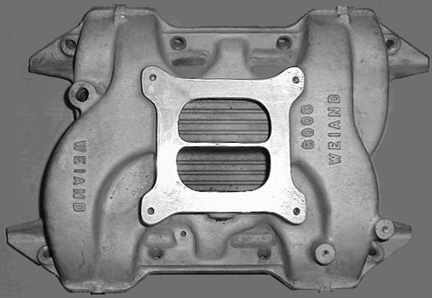
Dual-Plane Manifold |
Weiand Stealth for Mopar B |
Generic Cross-Sectional View |
 |
 |
Type 3:
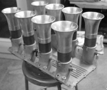
The Isolated Runner manifold is not standard equipment on any domestic V8, but common on earlier high- performance 4, 6, 8 and 12 cylinder imports and racing Cobras (289 & 427), typically using dual-throat Weber, Dell’Orto, Solex or Mikuni PHH carburetors. These are not true manifolds, as their only function is to connect 1 intake port to 1 throttle disc or slide. There is no commonality or sharing (except for a vacuum balance hose or passage for idle quality).
IR manifolds, where each cylinder can only draw from one barrel, offer the absolute best idle quality, throttle response, tolerance of high-overlap cams timing, and allow accurate tuning of intake length for maximum torque. The disadvantages are higher mechanical complexity, synchronization problems, limited under-hood space for intake stacks, and much higher manufacturing costs.
Even using the largest common IR carburetors (Weber 48mm IDA with 45mm venturis) the maximum cylinder size is about 45” (or 70 HP, whichever is less). The Weber flows about 330 CFM per barrel, giving a total of 2600 CFM, but this is barely enough to supply a 360” motor @ 7000 RPM. This is why IR manifolds have not been that successful in drag racing - even 2 Dominators aren’t enough to supply a 500” motor (62.5” cylinders) @ 10,000 RPM without some plenum to allow partial supply from other barrels. Completely separated IR carburetors for this motor would require 63mm (2.47”) venturis!
Larger motors will develop less power than with conventional tunnel-ram set-ups, due to inadequate flow capacity - each cylinder only “sees” 1 throat or barrel. There is no carburetor currently available large enough for 1 barrel to supply enough air for a 70” cylinder.
There have been IR manifolds (typically using 4 dual-throat Weber 48 IDA down-draft or DCOE side-draft carburetors) available for some V8 motors, especially Ford Windsor and FE, and small & big block Chevrolet. |
Most port fuel injection, such as traditional Hilborn, Enderle, Lucas, etc. “stack” injectors are isolated runner types. Stack fuel injection does not have the same maximum engine size limitation, as each throttle can be as large as 2.90” diameter! This is only possible with injection, as the low vacuum would produce inadequate signals for accurate carburetion. |
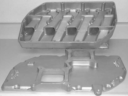
Isolated Runner Manifolds |
Fuel Injected 426 Hemi |
Generic Cross-Sectional View |
 |
 |
Reversion:
Each cylinder’s intake stroke actually begins when its intake valve opens, which is always while the piston is still rising at the end of the exhaust stroke (BTDC). No meaningful gas flow occurs at this point - the industry-standard convention is that effective flow begins at .050” valve lift. If the motor’s components are well chosen, at some useful speed gas will begin to flow into the cylinder even before TDC, despite the fact that the piston is going the “wrong” way. At speeds below this, piston motion tends to push the gas back into the manifold runner - this is called “reversion”. Generally, the degree of reversion depends on several factors, to a greater or lesser extent. The following Table gives factors and effects. |
Factor Affecting Reversion |
Increased Reversion | Reduced Reversion |
Single-plane manifold | Dual-plane, or divider plate |
Larger plenum volume or spacer | Turtle, stuffer or divider plate |
Larger carburetor | Reversion stubs below carburetor base |
Larger runner diameter | Longer runner |
Lower engine speed | Higher engine speed |
Higher compression | Lower compression |
Larger exhaust primary diameter | Reversion stub or step at flange | More overlap; small LSA or LCA (lobe separation or center angle); 102-110° | Less overlap; large LSA; 112-118° |
Advanced cam (intake opens earlier BTDC) | Retarded cam (intake opens later BTDC) | Low rod to stroke ratio (1.5 to 1.75) | High rod to stroke ratio (1.75 to 2.0) |
Vacuum:
Intake manifold vacuum is a very complex matter, affected
by factors not readily apparent. Vacuum is caused by the ratio between
2 separate volumes, which are “connected” when the intake valve is open, and the piston passes TDC on the intake stroke. During this interval, the (theoretical) 14.7 lbs. of vacuum in the cylinder is “satisfied” (partially returned to atmospheric pressure) by the volume of the entire intake tract before the remaining vacuum reaches the carburetor. Let “E” = the effective vacuum, “V1” = the volume of
1 cylinder, measured at full stroke length, and “V2” = the total volume of
the entire intake path: combustion chamber, intake port, manifold runner,
and plenum. Effective vacuum varies as the product of the cylinder volume divided
by the combined volume of the intake tract components:
E ~ V1 ÷ V2
Obviously, as the cylinder volume goes up
(larger motor displacement), or intake port, manifold runner or plenum
volume go down (dual plane manifold instead of single plane, etc.),
the ratio V1 ÷ V2 is high, and vacuum is improved, and a relatively high percentage of the original vacuum is available at the carburetor to draw in fresh mixture.
The reverse is also true: as the cylinder volume
goes down, or intake port, manifold runner or plenum volume go up,
the ratio V1÷ V2 is low, and vacuum is reduced, and the vacuum present at the carburetor is a smaller percentage of the original. The signal (demand) at the venturi and discharge nozzle is lower, resulting in a lean condition. |
Compression ratio
Another factor is combustion chamber volume.
Although this may be only a small percentage of the V2 total, it’s always present,
and its size affects vacuum. To demonstrate the practical range of chamber
volumes, it may be as small as 7.1% of the cylinder volume (CR = 15:1), or as large as 20% of the cylinder volume (CR = 6:1). If
the intake manifold is very small (“IR” type, with minimal internal volume),
the effect of a change in combustion chamber volume will be much greater
than if a tunnel ram manifold is used (where the plenum volume is typically larger than the cylinder volume). This is one reason why tunnel ram motors typically
don’t require major re-jetting for compression ratio changes, but a single-cylinder motorcycle with a single Mikuni will experience a sharp drop in response if compression is reduced (exactly as if intake manifold volume had been increased), unless jetting is revised to cure this lean condition.
The above analysis is only relevant under theoretical
conditions, where the cylinder volume is constant regardless of cam timing.
Add the dynamics of the real world, and it’s no longer accurate. The “effective” (true, or corrected) cylinder volume is dramatically
affected by changes in the closing point of the intake valve. For more detail on this subject, click here
to see my “Cam Timing vs. Compression Analysis” article:  . .
Late (radical) intake valve closing therefore adds another
negative effect on vacuum: reduced intake manifold vacuum at low to moderate speeds.
Even though the theoretical cylinder volume remains constant, the “effective” cylinder is actually
much smaller at the point where it’s “sealed” - the intake valve closing
point, which has the same effect on vacuum as on compression: a cylinder
of smaller volume. The volume of “effective” cylinder varies with the intake valve’s closing point; it’s always smaller than the theoretical cylinder because all modern cams close the intake valve ABDC.
In slow motion, at low to mid-range engine speed: there will be “normal” vacuum during
the movement from TDC to BDC with any cam timing, but as the piston
rises ABDC, some of this vacuum is satisfied by a smaller “positive cylinder”
(the piston’s motion from BDC to intake valve closing point), rather than
by incoming mixture from the manifold. This “positive cylinder” (its bore is the cylinder diameter, its stroke is measured from BDC to the intake valve closing point) may be
as much as 1/3 of the total cylinder volume with very late intake
valve closure (e.g. 80° ABDC). The result is reduced ability to produce
vacuum in the manifold, and therefore less accurate metering at the carburetor
and a generally lean condition. A delay in intake closing of only 5° will probably not be noticed in most applications, but a delay of 30° will almost certainly require more accelerator pump discharge, richer primary jetting, revised primary throttle disc position at idle, etc. At higher speeds, this factor has much reduced effect, and almost completely vanishes with large-volume manifolds.
|
Common Manifolds, By Application:
Here are some of the more common Mopar intake manifolds, sorted by Type and manufacturer. Non-Mopar manifolds (where listed for comparison) are marked “(N-M)”. |
Intake Manifolds |
Type |
Manufacturer |
Model Name, Number or Application |
Single-plane |
Edelbrock |
Tarantula, Torker, Torker II, TM-5, TM-6, TM-7, Victor, Victor W2 |
Holley |
Street Dominator, Strip Dominator |
Weiand |
X-Celerator, Team G |
Offenhauser |
Port-O-Sonic |
Chrysler |
NASCAR
Some M1 |
| Divided single-plane |
Weiand |
Hi-Rise |
Offenhauser |
360 Equa-Flow |
Chrysler |
273, 318 LA 2 bbl. (*some models)
273 4 bbl.
318” polyspheric A dual-quad
331, 354 & 392” early hemi 1955-58 dual-quad
350, 361 & 383” 1958-62 B dual-quad
413” 1959, 1962-64 RB dual-quad |
| Tunnel-ram |
Edelbrock |
TR, UR, Victor Ram (different tops) |
Holley |
Pro Dominator (different tops) |
Weiand |
Hi-Ram (different tops) |
Offenhauser |
Tunnel Ram (different tops) |
Chrysler |
Some M1 |
| Cross-ram |
Edelbrock |
STR (different tops), Smokey Ram (N-M) |
Weiand |
Cross-Ram (different tops) |
Mickey Thompson |
X-Ram (N-M?) |
Offenhauser |
Ram |
Chrysler |
413” Chrysler 300F & G 1960-61 dual-quad
361, 383” Fury, D500, Adventurer, etc. 1960-61 dual-quad
413, 426” Max Wedge, Ramcharger dual-quad
A990 Race Hemi dual-quad |
Chevrolet |
Z28 Option (N-M) |
| Dual-plane |
Edelbrock |
LD-340, CH-4B, DP-4B, Streetmaster, Performer, Performer
RPM
6-Packs: LD-6B (LA), DP-6B (B), CH-6B (RB)
Dual-Quad: CH-28 |
Holley |
Contender |
Weiand |
Action Plus, Stealth |
Chrysler |
Street hemi dual-quad
Street hemi M1 single 4 bbl.
6 Pack
Most 4 bbl.
Most 2 bbl. (except *, above)
Some M1 |
| Isolated runner |
Hilborn |
Port injection |
Crower |
Port injection |
Lucas |
Port injection |
Kinsler |
Port injection |
Enderle |
Port injection |
McKay |
Weber (N-M) |
Moon |
Weber (N-M) |
Ford Motorsport |
Weber (N-M) |
See these Victory Library booklets |

| 
| 
| 
| 
| 
| 
| 
| 
|

| 
|

| 
|

|
Intake, Manifold, single plane, dual plane, single-plane, dual-plane, tunnel ram, tunnel-ram, compare, analysis, cross ram, cross-ram, vacuum CFM, carburator, capacity, flow, reversion, formula, calculate, plenum, power, Holley, Carter, 4 bbl., dual quad, Victory, panic, Diamond, ejit
|