|
|
 |
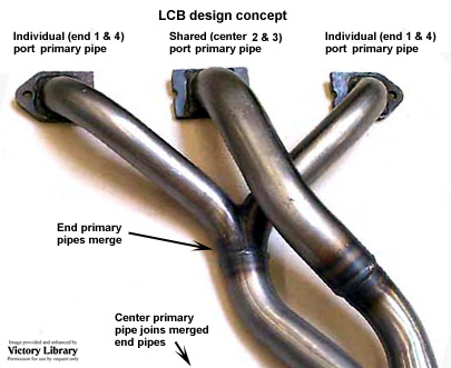
Exhaust header design using individual primary pipes for each cylinder has been fairly well examined elsewhere. However, this is generally specific to engines with an individual exhaust port for each cylinder, and cannot be directly applied to many older engines with common or “siamese” center exhaust ports such as the BMC A Series (Mini, &c.), B Series (MG, &c.) or other in-line four cylinder engines including both pushrod OHV and side-valve types. These engines have the center exhaust port shared between the #2 & 3 adjacent cylinders. |
One method of compensating for this is known as the “long center branch”
design, where the individual primary pipes (from the end cylinders: #1 & 4) are merged into a pair rather quickly, as found in “tri-Y” (4-2-1) systems. Their length is ½ of the calculated “tuned length” for the RPM needed for peak power.
The shared port (from the center cylinders: #2 & 3) has a somewhat larger |
|
|
diameter primary pipe. This is because the port is pressurized by the two center cylinders in rotation every 360°, and added area is needed to reduce residual pressure. Based on the pipe sizes normally found in these engines and the commercially available sizes, the common pipe is about 1/8” (.125”, 3.2mm) larger OD than the individual pipe OD for smaller engines, and about 3/16” (.1875”, 4.8mm) larger in larger engines.
The shared primary pipe is the full calculated length (viz., about twice the length of the individual primary pipes), and join the pipes from the other cylinders after they merge. Here’s the concept, shown above right; click on the picture for a larger image. |
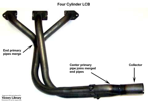
To predict the required pipe size the usual rule of 300 feet per second gas speed at peak power works fairly well for the end cylinders (1 & 4) but not for the shared ports, since not only is the gas volume higher but the timing of port pressurization depends on the firing order. Shown, right, is the entire LCB header and collector system; click on the picture for a larger image. | |
|
The Table below shows suggested pipe OD sizes for four cylinder engines by maximum displacement, rounded off to the nearest 1/16” increment. These sizes were developed by David Vizard, and are therefore empirical and practical (rather than calculated and theoretical), and should be used in preference to a size derived by formula. The pipe ID must, in all cases, be the same size or larger than the actual port ID - never smaller. Make no attempt to taper, radius or transition the exhaust port larger to match the primary pipe ID, as an abrupt “step” is the proper shape. |
Table 1: Four cylinder engine; size vs. exhaust pipe OD |
Maximum size, CC |
828 |
933 |
1,042 |
1,159 |
1,281 |
1,544 |
1,831 |
2,143 |
2,480 |
2,841 |
Cyls. 1 & 4 OD, inches |
1-1/8 |
1-3/16 |
1-1/4 |
1-5/16 |
1-3/8 |
1-1/2 |
1-5/8 |
1-3/4 |
1-7/8 |
2 |
Cyl. 2-3 OD, inches |
1-1/4 |
1-5/16 |
1-3/8 |
1-7/16 |
1-1/2 |
1-5/8 |
1-11/16 |
1-15/16 |
2-1/16 |
2-3/16 |
|