|
|
 |
Log Intake Manifold Construction Ideas
Purpose
Log manifolds as manufactured “back in the day” were, generally, designed for racing, have poor idle quality, un-even mixture distribution, and require expensive and complex linkage to function properly. The world’s fastest fuel dragster (Cook-Bedwell Isky/U-Fab Special Chrysler 354) used one in 1956.
Complete fabrication of a log manifold with somewhat better “manners” can be done using standard commercial shapes (plate, cylinders, &c.). It’s possible to do this in steel (16 gauge or heavier), but aluminum is prettier, easier to port and radius when complete, and saves some weight (the flanges are heavy). My choice would be 6061 alloy, as it’s common, weldable and relatively inexpensive to find in odd shapes. |
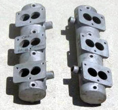
The same general construction as used 50 years ago will still work: two pieces of plate become the port flanges. Of course, an in-line engine (4, 6, 8) will only have one flange and one plenum with a single row of runners. More wall thickness (¼” instead of 1/8”) on all pieces adds weight and expense, but makes for easier welding, more strength, more thread depth if needed, and allows intersections and joints to be radiused. One bank of a fabricated Cragar log manifold for a Cadillac |
|
|
with the then-popular Stromberg 48/97 3-bolt base flange bolt pattern is shown here. Notice the stubs on the right side for vacuum balance. Click the picture for a larger view.
Two lengths of ½” or heavier plate form the flanges. Eight short lengths of box-section tube with the ID matched to the intake port size form the runners between the flange and the plenum.
Plenum volume
Two 2¼” to 3½ OD cylinders form the plenums: one for each bank of cylinders. The plenum length should extend past the last port runner at each end by 1” or so. The plenum volume is a function of the number and displacement of the cylinders it feeds: 25% of the total displacement (half of one bank of cylinders) on a “V” engine, 50% of the total displacement of an in-line engine; smaller if using 6 carburetors, larger if using 2, etc.
To use this table, measure your intake manifold length from the outside of the end ports (1-4, 1-6 etc.), add 2” minimum, and locate this distance in the left Column. Go across that Row until you reach 25% of your V8 engine displacement or 50% of your 6 cylinder engine displacement for your plenum tube ID. If you have a choice, larger diameter is preferred to greater length.
Example: your engine is a 283; 25% of that is 71”, your flange length is 16”, add 2 is 18”. Go down Column 1 to 16”, then across that row to find 71”. The closest diameter is 2.25” |
Plenum volume as a cylinder |
Plenum ID | 2.25” | 2.50” | 2.75” | 3.00” | 3.25” | 3.50” |
14” long | 56” | 69” | 83” | 99” | 116” | 135” |
16” long | 64” | 79” | 95” | 113” | 133” | 154” |
18” long | 72” | 88” | 107” | 127” | 149” | 173” |
20” long | 80” | 98” | 119” | 141” | 166” | 192” |
22” long | 87” | 108” | 131” | 156” | 183” | 212” |
24” long | 95” | 118” | 143” | 170” | 199” | 231” |
26” long | 103” | 128” | 154” | 184” | 216” | 250” |
Volume is a rather imprecise terms when analyzing a plenum.
As interior space increases (vs. cylinder volume) the buffer or anti-reversion effect increases, but this isn’t linear and probably decays to a minimum value with some multiple of cylinder size.
As interior space increases the vacuum signal to the nozzle also decays, requiring accelerator pump shot, jetting, and air correction changes.
Volume’s effect on power decays to zero as the carburetor total CFM approaches 100% of engine capacity at perhaps .5- 1.0” Hg signal at the nozzle. If the carburetors are much too small, more plenum volume helps quite a bit. This was known 30 years ago: Jenkins remarked that 2 × 660 was enough for a 355” engine with a big plenum, the mini-plenums using 2 × 4500s weren’t offering any advantage, and an IR with 2 × 4500s lost power.
There is, IMHO, a minimum distance from the end of the runner re-entrant into the plenum floor, this must be at least 1.5 × runner ID. Obviously, all plenums I’ve seen exceed this.
Ideally, each runner entry should also have unoccupied floor radially with OD about 2.5 × runner ID. This insures separation of the wave signals, and allows maximum wave energy recovery since the runner wave sees this as “open”. Can’t be done on engines with paired runners without a lot of curves and enough runner length to make the curve at big radius. A tube in open air can pull from almost behind (viz. 180 degrees) its entrance, and the best runner end shape is a shallow or non-tapered stack ending in a 270 degree roll-over radius, 1/4” minimum. It should end one radius minimum above the floor.
I know of plenums built way over-size with dual purpose: easier complex mods after testing (stuffers, extend the runner lengths inside, change the relative runner entry positions), and to completely confuse rivals who couldn’t figure out how a refridgerator that big could work. Imagine a plenum large enough that really long runners pass each other inside...
More ½” plate forms the base plates for mounting multiple carburetors (even number only: 2, 4, 6 or 8; my preference is 6), although lots of work can be saved by simply welding or bolting commercially available manifold adapters with the correct carburetor base flange pattern directly to the upper surface of the plenums. The bases for the primary (center) carburetor(s) can be made 2” wider (inside, outside, or both) to allow for mounting linkage, return spring, fuel distribution block, fuel pressure gauge, &c.
The crossover connecting vacuum hose slips over the two stubs. Water bypass stubs will be needed when the heads have no other water circulation than across the manifold; see the service manual for the correct water paths for your motor and water pump type.
The angle where the port runner intersects the flange is important here as well, as described earlier. The runner should “give back” the incline, and meet the flange at 90°, minus the incline angle. This establishes the manifold runners at the same position as in the original manifold.
The port runners must also be sized & shaped to match the port opening. Depending on your motor, some tubing’s ID will come closer than others to the actual port dimensions. This is the single most difficult part - locating the right rectangular tube at reasonable cost. If you can’t locate any in the right size, you’ll have to either use two open (“U” shaped) channels and weld them face-to-face, or use a slightly smaller size with thick walls, and port it.
Round tubing can also be used, as long as the transition to the actual port opening in the flange is very gradual with a shallow taper. The entry into the plenum can be left round.
The inside surfaces where the runner meets the flange opening should be blended and radiused to remove any sharp edges or obvious irregularities.
The base flanges should be an exact match of the head’s intake port surfaces, including bolt holes, port size & shape, and water transfer holes. Make sure the flange port openings are not larger than the head; slightly smaller is acceptable. Thick flanges allow the water transfer stubs to be threaded in place (rather than welded) if you wish; use a brass pipe fitting and remember to apply Nevr-Seize, &c. to prevent corrosion. |
Table 1: Log Manifold Materials |
Component | V8: # Needed | 6: # Needed | 4: # Needed | Shape | Suggested Dimensions (L × W × T) |
Base flange | 2 | 1 | plate | 20” × 2-1/2” × 1/2” |
Plenum | 2 | 1 | cylinder | 20” × 2-1/4-3” OD × 1/8-1/4” wall |
Plenum end cap | 4 | 2 | round plate | 2-1/4-3” OD × 1/8-1/4” |
Port runner | 8 | 6 | 4 | rect. tube | 1-3/4” × 1-1/2” × 1/8-1/4” wall |
round tube | 1-1/2” × 1-1/2” × 1/8-1/4” wall |
Carburetor base, primary | 2 | 1 or 2 | plate | 4” × 5” × 1/2” |
Carburetor base, end | (4) | 2-5 | plate | 4” × 3” × 1/2” |
Vacuum hose stub | 2 | 1 | tube | 2” × 1” OD × 1/8-1/4” wall |
Water transfer stub | 4 | ? | tube | 1” × 1” OD × 1/8-1/4” wall |
The cylindrical plenum can be split horizontally to make fitting the intake runners easier; here’s a manifold in fabrication by Gear Drive Speed & Custom Specialties; click for a larger view.
The upper end of the runners can enter and join the floor of the plenum in several different ways. I’ll give them in order of simplicity.
1. Contour the runner ends to match the plenum’s wall curvature for a tight fit, and butt weld. Drill through the plenum wall, and enlarge the hole |
|
|
with a die grinder to match the runner shape. The result, as seen from inside the plenum, is a flush joint.
2. Pre-radius the runner’s plenum end before performing Step 1. to form a 3/8” radius where the plenum wall meets the runner ID.
3. Make the runner longer by about ½” + the wall
thickness of the plenum. This will put the upper end ½” inside the tube ID. Radius the end into a bell.
4. Add a “½-donut” with 3/8” radius to the runner’s entry point on the floor of the plenum. The donut radius should end at the floor and the donut extend up by ?”.
For the best finish and ease of construction, as well as appearance, lots of simple hand work is required to inlet, radius, bevel, &c. all the tubes to make the intersections almost seamless before welding.
When complete, the manifold can be polished to a degree not possible with a cast manifold - makes a real eye-catcher!
Although traditional log manifolds had multiple large-diameter “vacuum balance” hoses connecting the plenums, in my opinion this is a mistake. If modern carburetors are used, each bank of cylinders is capable of idling on its own, much like many factory 360° divided single plane manifolds, where only a small notch connects the left & right sides. A 1” ID balance tube centered between the primary carburetors should be more than enough. If the connection is larger, the vacuum signal to both primary carburetors is reduced (each “shares” the demand of all eight cylinders, instead of just the four in its own bank).
A homemade manifold can match the performance of a commercial piece. However, there are some choices that are not as “open” as they seem:
1. the log or plenum volume makes up for small carburetors, but also cleans up mixture distribution somewhat (where the carb position isn’t ideal vs. the intake ports)
2. if it’s too big response suffers, rich jetting and a big accel shot is needed
3. if it’s too small - peak power is down
4. the need for a balance tube between left and right banks was not well understood back in the day, and IMHO it’s unnecessary.
5. for each carb to flow like the others there must be open room under the base in all directions - the plenum must extend past the carb opening by at least 1”, preferably 1/2 the carb size.
6. if the carbs are big enough and the plenum volume (especially the X-section area between carbs) is small the carb placement will be very important - this is a mistake made even with commercial manifolds
7. the “stagger” (forward placement of 1 log) is generally about 1” (the width of a connecting rod), but use the actual distance between your #1 and #2 ports.
Don't be creative - try to imitate something that works.
A manifold for a much larger engine is generally not a great idea, so restrict the plenum/log volume by dropping the diameter by 1/2” etc.
I had an idea of how to deal with plenum volume for a Harley install some time back, and couldn’t figure out why the volume had to be between the carb and the engine - and couldn’t get an answer.
It turns out - it’s doesn't have to be. The “balance tube(s)” (which are, of course, plenum volume) can be sized to change total volume after the manifold is built for tuning.
Do this by making a stub entrance in each log (facing inside) 1-1/2” to 2” and simply making a central tube with screw-on or hose-clamp ends with the same size stub (they don’t have to be the size of the log, or the connector).
Example: a 327” motor uses a total of 48% plenum volume: 24% each in 2 logs each 2-1/2” OD by 18” long (1/16” wall).
A 4” tube 8” long connecting the left and right sides adds another 95", raising the volume to 255” or 78%. Too much? Use a smaller tube, just unscrew the clamps.
The stub should enter the logs near the top and the connector near the bottom to prevent gas pooling.
Multiple Carburetor Choices
Stromberg
The carburetor of choice for many years was the Stromberg 48 and 97, which have a 3-bolt base flange bolt pattern (see below for details). They were easily available and (since larger carburetors hadn’t been invented yet) adding extra ones was the only effective way to increase total airflow. However, these are now relatively rare, obsolete and expensive museum pieces, and don’t flow as much air as more modern replacements. |
Table 2: Stromberg 2 Bbl. Data |
Type | Venturi | Venturi area (both) | Flow @ 3” Hg | Flow @ 1.5” Hg |
48 | 1-1/32” | 1.03125” | 1.671” | 240 CFM | 170 CFM |
L | 1” | 1.0000” | 1.571” | 222 CFM | 157 CFM |
97 | 31/32” | .96875” | 1.474” | 204 CFM | 145 CFM |
81 | 13/16” | .8125” | 1.037” | 127 CFM | 90 CFM |
Rochester 2G
The obvious replacement is the Rochester 2G, 2GC & 2GV (as used on Chevy 348 & 409, Cadillac Eldorado, Olds J2 & 442, and Pontiac tri-power). These are common on V8 motors from the 1960s and 1970s, much less expensive (used carburetor on eBay: $10.), easier to tune & repair, and available in five sizes, all of which have higher air-flow capacity than the Strombergs. It’s a bit big for ease of mounting: the small flange bolt pattern is 3¼” × 1-3/8” (also referred to by its SAE flange size of 1¼”); the large flange bolt pattern is 3¾” × 2” (its SAE flange size: 1½”), and two of them used for idling flow more air than needed.
If you decide to use these, get the smaller bolt pattern with the 1-7/16” throttle bore.
They’re easily modified to increase CFM by the usual methods. Try to get the model with the side-mounted fuel inlet for clearance in between the carburetors. The primary (center) carburetor can be up to three sizes smaller than the two end carburetors for best idle quality, part-throttle response and gas mileage. |
Table 3: Rochester Model “2G” 2 Bbl. Data |
Type | Throttle Bore | Venturi | Venturi area (both) | Flow @ 3” Hg | Flow @ 1.5” Hg |
Small | 1-7/16” | 1.4375” | 1-3/32” | 1.09375” | 1.879” | 278 CFM | 197 CFM |
1-5/32" | 1.15625" | 2.100" | 311 CFM | 220 CFM |
Large | 1-11/16” | 1.6875” | 1-3/16” | 1.1875” | 2.215” | 352 CFM | 249 CFM |
1-1/4” | 1.250” | 2.454” | 381 CFM | 269 CFM |
1-5/16” | 1.3125” | 2.706” | 423 CFM | 299 CFM |
1-3/8” | 1.375” | 2.970” | 435 CFM | 308 CFM |
For those with money, the Holley 2300 2 bbl. is physically much larger (flange bolt pattern: 5-1/8” × 3½”) and harder to mount, and much more expensive since it’s OEM on more modern 6-pack motors.
The Holley 2305 2 bbl. (available in 350 & 500 CFM) is a modern, tunable carburetor with a progressive secondary throat; this means that only one barrel is used for idling, the other “kicks in” on demand, permitting better idle quality. Two of these (one on each bank) means the motor will idle on two primary barrels, just like a normal V8 with a 2 bbl. carburetor. However, they’re rather large, and will be awkward to mount, and not “traditional” looking.
Another possible is to use six modern 1 bbl. carburetors from a six-cylinder motor. The Rochester Monojet “M” is very common 1968-*, and available in 1-7/16” & 1-11/16” throttle bores. Even though it’s a 1 bbl., the throttle bore size is much larger than the Stromberg 2 bbl. These are not suitable to use as “tri-power” on a single manifold. The cost is very low (used carburetor on eBay: $5.) and parts are easily available. This will be the easiest to mount, as the 2-15/16” 2-bolt base flange bolt pattern has a smaller “footprint” than a 2 bbl., but jetting advice is harder to come by. Low accelerator pump volume may be a problem.
“Rochester Carburetors” by Doug Roe is a complete guide to jetting and adjustment here:  . .
Let’s compare the Monojet “M” to the Stromberg 2 bbl.: |
Table 4: Rochester Monojet 1 Bbl. Data |
Type | Throttle Bore | Venturi | Venturi Area | Flow @ 3” Hg | Flow @ 1.5” Hg |
M small | 1-7/16” | 1.4375” | 1-7/32” | 1.21875” | 1.167” | 160 CFM | 113 CFM |
M large | 1-11/16” | 1.6875” | 1-5/16” | 1.3125” | 1.353” | 210 CFM | 148 CFM |
1-1/2” | 1.500” | 1.767” | 250 CFM | 177 CFM |
For larger motors (350-400), a mid-size 1-5/16” venturi (148 CFM) can be used as the center (primary) carburetor, with larger 1½” venturi (177 CFM) end carburetors on progressive linkage for only 296 CFM at idle (about the same as a 2 bbl.), but over 1000 CFM at full throttle (although each cylinder bank only uses 500 CFM).
Mid-sized motors (300-350”) can substitute the 17/32” venturi (113 CFM) as the center carburetor, with larger 1-5/16” venturi (148 CFM) end carburetors for 226 CFM at idle, 818 CFM at full throttle (each bank: 409 CFM).
Smallest motors (250-300”) can use the 1-7/32” (113 CFM) venturi in all three positions for 226 CFM idle, 678 CFM at full throttle (each bank: 339 CFM). Click here for multiple carburetor intake manifold linkage comments: .
Click here to read about adapting a manifold from another engine: |
|