Pump Orientation:
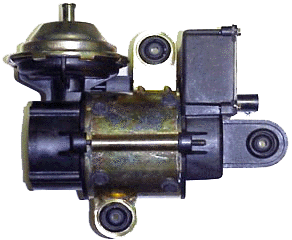
The pump should be mounted with
the rubber mount bracket on the top (4 screws secure it to the pump body). There are drain holes in the bottom of the pump that remove any moisture that might have collected inside the pump. If the pump is mounted at another angle, it will have a shorter life.
Mounting Bracket:
No mounting bracket is supplied with this pump. The pump was designed to be secured by a 3-dimensional bracket which bolted to the firewall or inner fender, etc. Since no 2 installations are similar, I can't help you with hints as to bracket shape or size. Try to determine the best place to put the pump before you start making the bracket. Remember that most brackets are strong in tension, but flexible in compression - if mounting the pump from below, the bracket must be stronger than if suspended (hanging) from a top-mounted bracket.
The rubber grommets (provided in the pump's mounting ears) reduce noise and vibration, and should be used. Use all 3 mounting holes if possible. Do not over-tighten the mounting bolts - the grommets are not effective if fully compressed. To keep the hoses short, the pump is usually placed close to the power brake booster cannister (driver's side fender or firewall). Look for existing bolts, brackets, threaded holes etc. in this area as potential points of attachment.
The bracket can be made of sheet metal (16 ga. & up preferred), aluminum flat stock, angle iron, wood, masonite, etc. as long as it will stand up to under-hood conditions and will support about 5 lbs. It may be easier to start with 90° corner brackets (common hardware store item) to attach to the pump's grommets; then the fabricated piece that ties them together can be a simpler shape. You could use 3 pairs of corner brackets: arrange #1 to align with a pump grommet, #2 is bolted to it in mirror position to form a "U". Do the other 2 pairs the same way. Now you have 3 tabs parallel to each other and above (or below) the pump body, so a single flat piece of material can tie them all together.
The final tie-in should be to substantial sheet metal or an existing bracket. Look for a fender brace, wiper motor bolt, etc. and replace it with a longer bolt if necessary. Try to keep bending force to a minimum by making the highest point of attachment to the car centered above the pump body as much as possible, or attach a strap between the top mount and the overhanging grommet.
Hose Connections:
To connect the pump to the
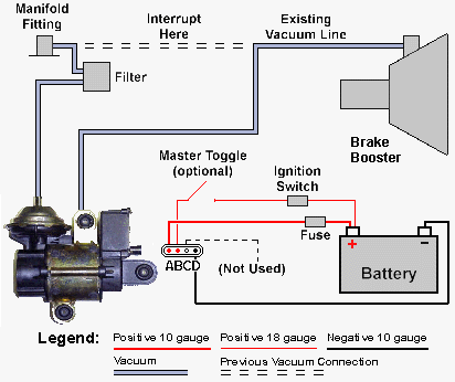
existing vacuum hose, remove the hose from the booster (leave it attached to the intake manifold). Connect the free end of this hose to the pump exhaust (gold-colored metal can on the side, with a hose fitting protruding). In the original installation there's a small (carbon) filter just before the pump (Vacuum Filter #675-5136, retail $10.60, net $7.99 from NAPA, or GM). This is a good idea - if you're going to use this, the hose goes from the manifold to the filter, then to the pump exhaust.
A new hose goes from the suction side of the pump (black rubber "T" fitting mid-way on the pump body) to the booster. This way the pump is installed between the motor and the brake booster. The pump has a pressure switch so it will not turn on unless the pressure gets below about 5 pounds. Idling around in town the pump often comes on. If the engine stalls (manifold vacuum rises to ambient air pressure), and the key is still on, the pump provides all the vacuum. Some owners install a switch to disable the pump until they need it. A side benefit of the pump is that if your booster has developed a leak, the pump will run continuously to make you aware of a problem
before an emergency occurs.
Some owners "T" the pump into the vacuum hose between
the manifold and the booster. Installed this way, the engine sucks through the pump, to the booster. This would require a check valve in the booster hose ahead of the pressure switch to keep
the engine from drawing down the pump vacuum if the motor stops. The pump will not be able to draw a vacuum in this configuration if the engine stops because the engine will bring the booster up to ambient air pressure. The only time the pump comes on is when the vacuum is too low and then it helps the engine vacuum.
Electical Connections:
Try your local auto store (or GM, wrecking yard,
etc.) for the electrical plug that goes to the pump. From left to right
on the lugs, the first lug (A)
is 12 volt (+) constant. The second one from the left (B)
is 12 volt (+) from the ignition switch and/or toggle switch.
The fourth one (D) is 12 volt (-) negative ground.
-
Connection A (Red wire, in the original harness) to the battery positive (12 volts +), heavy (10 gauge) wire through a fuse.
-
Connection B (Black with white stripe)
to the ignition positive (12 volts +), light (18 gauge) wire
-
Connection C (plugged) not used (not
used in factory system either)
-
Connection D (Black wire) negative
ground (12 volts -), heavy (10 gauge) wire
The pump is powered via the A
connection, but will only run if it receives power from the ignition switch
on the B connection. If you wish, a
manual over-ride switch (with the key "off" or on "accessory") can be used
as a second source of 12 volts to the B
connection to power the pump on demand. This may be useful for towing with
the motor off, so that you still have power assist. For safety, a relay can be placed in between the fuse and the pump to control power to the A terminal, with the control wire patched into the B connection to the ignition. This will keep power from reaching the pump at all until the ignition is on.
Other useful parts to assist you with your installation:
» toggle switch (single pole, single throw OK)
» fuse or circuit breaker (10 amp)
» 10 amp relay for main 12 volt source
|


