|
|
 |
Harley-Davidson 45 Solo Frame Modification Ideas
Purpose
The 1941-52 45 solo frame, although the
strongest of the series, have an unfortunate tendency to develop a crack on the right side at the junction
of the seat post tube and the transmission cradle casting. This is frequently precipitated by racing, where
the power and G forces apply leverage from the rear wheel to this area.
The methods
by which the frame can be made stiffer are very limited since most of the
critical area is two-dimensional. |
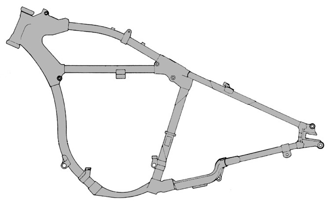
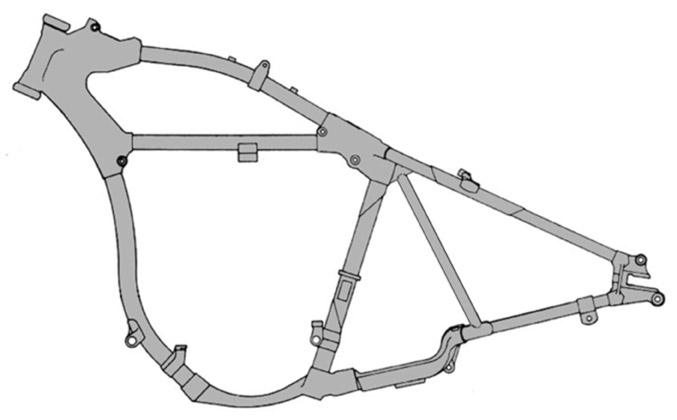
Here is a stock frame.
Note the large open area between the seat post and rear axle. The open
area surrounding the motor is not as fragile as it appears since
fortunately the motor itself provides considerable rigidity; this area
would be difficult to re-inforce in any case. Click the picture to open a
full-size image on a separate new page for more detail. |
|
|
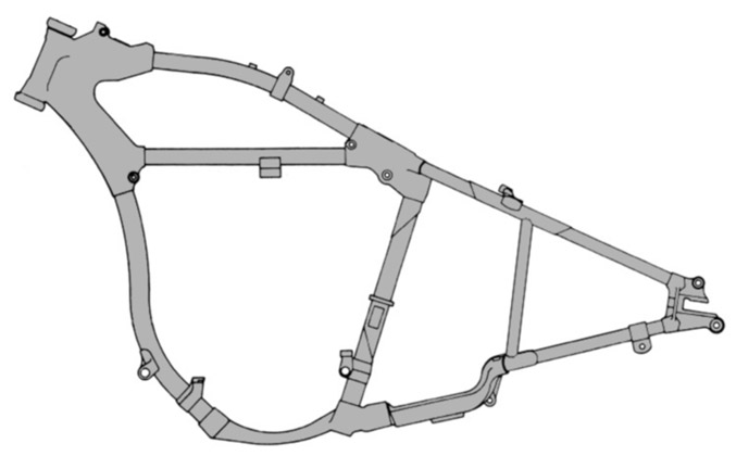
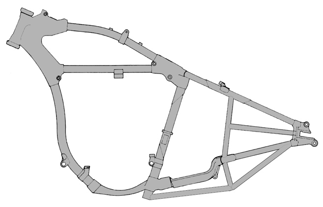
Here is a stock frame
with WR-type struts added between the upper and lower rear tubes on each
side. Note that the struts are not vertical, but angled to close the
upper and lower tubes into an isosceles triangle. The open area is now
much reduced. Click the picture to open a full-size image on a separate
new page for more detail. | |
|
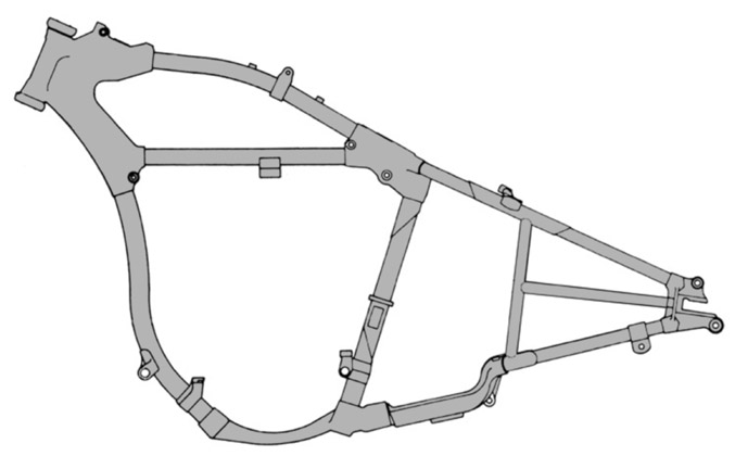
Here is a stock frame
with WR-type struts added between the upper and lower rear tubes on each
side, plus an extra horizontal bar on the drive (chain) side as used in
hill-climb machines (in this example both sides are done). Click the
picture to open a full-size image on a separate new page for more
detail. | |
|
Here is a stock frame
with forward-angled struts added between the upper seat post lug and lower
rear tubes on each side, as suggested by Milwaukee Belle; click here for his web site:  .
This transfers
the load better than the near-vertical struts shown above, but at the cost
of compromising the space normally containing a battery box, oil tank,
etc. For magneto-equipped machines .
This transfers
the load better than the near-vertical struts shown above, but at the cost
of compromising the space normally containing a battery box, oil tank,
etc. For magneto-equipped machines | |
|
with oil in the tank this will prove
more effective. Click the picture to open a full-size image on a separate
new page for more detail.
However, although
partially effective in reducing breakage an improving handling,
re-inforcing the frame as shown only resist flexing and the natural
counter-clockwise rotation of the transmission against torque in a
vertical plane. |
Here is a stock frame with forward-angled struts, and an under-brace added between the axle plate and an extension built off an insert hrough the seat post tube. Click the picture to open a full-size image on a separate new page for more detail. | |
|
There have also been
reports of breakage of the right lower tube ahead of the axle plate. This
may have been due to brake load transmitted from the rear backing plate.
Even though this is the most convenient location, there is no reason why
the backing plate can't be linked to the frame much farther forward to
transfer the load to a stronger area such as the the outboard 3rd
transmission | |
|
stud. The original hole in the backing plate’s tab
(originally used to bolt through the frame tab) can be the attachment
point of a heim joint, then a tube leading to a 2nd heim joint. This
location is far from the best choice, but at least it will reduce the
bending stress on the right rear leg. Click the picture to open a full-size image on a separate
new page for more detail.
Click here for some ideas on improving the rigidity of the
engine-to-transmission lock-up:
|
Wheel choices
The alloy Sportster rim is the best bang for the buck, very strong, easy to find used (sometimes cheaper with the wheel still assembled). The flange collects dirt which adds weight and affects balance so a bit more maintainance.
A Sun, Excel etc. (not flanged) rim is slightly lighter, more expensive, hard to find used - not sure how much weight difference.
If you use an 18” rim and find yourself with less lean angle than you need, the engine height is probably OK (except for the pipes), but you can shim the transmission up slightly which will raise the bottom of the primary under the clutch drum without escaping the cradle effect. For more room, add a flat steel or aluminum block (shaped like the cradle extension) under the transmission, attach it from underneath with countersunk screws to the case, and use longer studs.
The mounting tab on the primary cover can also be extended or simply slotted to allow it to be bumped up a bit until the chain just clears the inner surface. Trim the inner lip down, and elongate the cross-shaft hole.
Alternate rear wheel
Mid-sized Honda etc. rear wheels offer a much wider choice of sprocket sizes in the same chain pitch as the 45 (#50, 530 etc.), and are easy to find as complete wheels, hubs, brakes etc. cheap. Try to get only the hub to save shipping. The holes can be enlarged to fit 8 gauge spokes. IMHO a 36 hole wheel is strong enough. The rear brakes run around 180mm (7.1”), but I think this is larger than the 45? If yes, you want the next smaller size which is probably 160mm (6.3”), which means a 160, 175 etc. You can take a lot of weight off the drum with an 8” lathe.
The sprocket will be on the wrong side, so turn the wheel over. You need a cross-over shaft (best) or cable to attach your brake pedal to the brake cam lever on the backing plate. The leverage between the pedal and arm may be way off (either not enough travel, or not enough effort applied), so be prepared to drill extra holes to change this. The existing rear support shaft could be replaced by a hollow tube to house a cross-shaft, fair amount of work but this allows the brake pedal to pivot off the shaft - saves weight and parts.
A new cross-shaft can be as simple as a piece of thick-walled tube welded to the frame with roller bearings in each end. There isn’t much room for this, and I suggest it not be welded to the seat post at the bottom which is a known weakness. The shaft should be the same length as the lateral distance between the pedal and brake arm. I suggest using a splined shaft as a donor since this allows “clocking” one end for rotation in small steps. The links to the pedal and brake arm should be Heim (rose) joints, not clevises.
Wheel total weight is more important on the front since it’s unsprung; rim weight is more important on the rear (inertia). |
|