|
|
 |
In this series, I will not repeat the information that is already available on how superchargers work, but instead focus on their selection, installation, use and tuning on older motorcycle engines. Here I will make various observations and comments on function, and in some cases how to make improvements. New material will be added regularly, and eventually better organized. Click below to jump directly to an individual topic. |
Supercharger Topics | |
Function |
|
|
|
|
|
|
|
|
Supercharger Drives |
A mechanical connection must be made between the engine and the supercharger’s drive end. To keep efficiency high and parasitic losses low, the supercharger is normally mounted with its shaft axis parallel to the crankshaft, although 90° drives have been used successfully by Magnuson and others. This alignment must be precise or wear, vibration and breakage will result. Less than 1° misalignment out of parallel should be the target. Remember that this includes both planes: roll (rotation around the wheelbase axis) and yaw (rotation across the lateral or crankshaft axis). Many superchargers are tolerant of pitch angle (inclination or “clocking” around its own shaft axis), which provides some additional leeway for exact placement &c.
Vibration-free “isolastic” mounts are theoretically possible, but the complexity of making a subframe to mount the engine, transmission, supercharger &c. together and then to isolate this from the chassis is more involved than the supercharger installation. I suggest that absolute rigidity is the best practical solution.
The supercharger will most frequently rotate at a higher speed than the engine depending on the supercharger design and its capacity relative to engine displacement, in some cases as much as triple the engine RPM (300% drive ratio, or 200% overdrive ratio). |
Drive source
Where may the supercharger be driven from? The choices are limited to two major groups: relatively simple, and more complex. Simple drive sources are the engine sprocket (drive) shaft, or the clutch shell (or drum). Both of these are strong enough to withstand added load, whereas the engine’s cam drive, generator drive, magneto drive &c. are not as well-supported in the engine (smaller bearings, shafts, &c.) and therefore generally not suitable.
The engine’s sprocket (drive) shaft is the obvious choice for an easy fabrication, except that its fairly small tooth count (typically between 17 and 29) limits the speed at which it can drive a supercharger directly. If a longer chain of the same type as the original primary drive (click here for more chain data and comparisons:  ) is run across all three sprockets (engine, supercharger, & clutch) the alignment and adjustment is simple but the supercharger sprocket must be the same size as the engine sprocket for 1:1 drive ratio, and much smaller to rotate the supercharger faster than the engine. E.g., a 28 tooth engine sprocket would need a 14 tooth supercharger sprocket for 2:1 ratio to spin the supercharger at 200% of engine RPM, and this tooth count is below the threshold of minimum size. 17 teeth is considered the smallest safe choice regardless of chain size. The chain “wrap”, or percentage of the sprocket OD which engages the chain, will also be less than desired. This can be remedied by use of an idler sprocket, which can also serve as an adjuster. ) is run across all three sprockets (engine, supercharger, & clutch) the alignment and adjustment is simple but the supercharger sprocket must be the same size as the engine sprocket for 1:1 drive ratio, and much smaller to rotate the supercharger faster than the engine. E.g., a 28 tooth engine sprocket would need a 14 tooth supercharger sprocket for 2:1 ratio to spin the supercharger at 200% of engine RPM, and this tooth count is below the threshold of minimum size. 17 teeth is considered the smallest safe choice regardless of chain size. The chain “wrap”, or percentage of the sprocket OD which engages the chain, will also be less than desired. This can be remedied by use of an idler sprocket, which can also serve as an adjuster.
Attaching another sprocket in parallel (alongside on the same shaft) with enough clearance between them for the chains to pass each other is an alternative, but the 2nd engine sprocket must still be larger than the supercharger’s driven sprocket. If the minimum S/C sprocket size is 17 teeth this means that the engine sprocket must be 51 for 1:3 ratio, much too large in diameter to be practical since even with small pitch chain the extra row will not clear the inside of the primary cover. The extra sprocket will also overhang the existing main bearing unless an outboard support is fabricated - a complex project in itself.
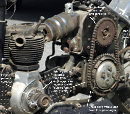
Driving a chain off the clutch shell by adding a 2nd tooth row removes the problem of diameter - the clutch is already large (typically between 42 and 58 teeth), but substitutes another. Since the clutch is only turning at a percentage (typically between 50 and 67%) of engine speed, the supercharger drive sprocket must reverse the primary drive ratio, as well as multiply clutch sprocket speed. E.g., a Triumph 29 tooth engine sprocket turns its 58 tooth clutch drum at 1:2 ratio (50%) of engine speed, so the supercharger drive sprocket must be 29 teeth (1 ÷ primary ratio) to run at 100% of engine speed and 14 teeth to run at 200%. |
Jackshaft
The drive ratio need not be accomplished by a single pair of sprockets or belts. A jackshaft or countershaft can “split” the ratio into two components which, when multiplied (not added) together produce the required drive ratio. Where useful, a combination of overdriven and underdriven sprockets may be used to take advantage of existing inexpensive, or easily available components. For example, a similar drive ratio may be obtained by any of the following choices: |
Countershaft ratio choices compared |
Split type | Sprockets, ratio 1 | Ratio 1 | Sprockets, ratio 2 | Ratio 2 | Final ratio |
Overdrive, split evenly | 28 + 20 | 1:1.4 | 28 + 20 | 1:1.4 | 1:1.96 |
Overdrive, split unevenly | 24 + 20 | 1:1.2 | 30 + 18 | 1:1.67 | 1:2 |
Overdrive + underdrive | 54 + 18 | 1:3 | 20 + 30 | 1:.67 | 1:2 |
This not only gives greater latitude in sprocket or pulley choices, but allows the driven end of the supercharger to be laterally opposite the engine component driving it. This also reverses the supercharger rotation, which is very helpful in many cases where the original application has the supercharger turning clockwise, such as most Eatons. |
| |
Here’s a jackshaft and its bearings built into the case of a twin rotor supercharger to both reverse the drive, and place the air entry forward. Click for a larger view.
Any two drive methods can be combined as well: drive the countershaft from the primary chain using the same type sprocket, then drive the supercharger from the countershaft using a serpentine belt using the original multi-rib pulley type. This allows drive ratio changes in very small increments, but of course adds weight, complexity, noise, size and requires twice the number of spares.
However, it allows the actual final drive chain to be located on a better vertical center (i.e. midway through the swing-arm travel) to reduce suspension bind on power application, so you can put the transmission where you want it rather than at the best height.
It allows really small gearing changes without taking the clutch apart or the rear wheel off.
It allows better sprocket tooth count on the transmission and rear wheel. By splitting the final ratio between 2 sets of sprockets you won't be faced with the problem of “they don't make one this size to fit my __________”.
It allows use of prime number sprockets to maximize chain and sprocket life.
It allows adjustment of chain without moving the rear wheel: the jackshaft slides forward and back, and is screwed or shimmed up and down for tension; adjusts both chains together.
It avoids using sprockets too small for best life (smaller than 17) or too big for good chain speed (more than 60).
Remember it has to be where you can check it for adjustment, lubrication, get the salt off, what will it wreck if it breaks, etc.
Don’t use a jackshaft unless you have to - the downside is minor power loss and more potential breakage.
|
Drive methods
The supercharger drive is most frequently roller chain, toothed belt (also known as Gilmer belt, cog belt, synchronous belt, &c.), ribbed (serpentine) belt, V belt, flat belt, gear, or direct. There are advantages and disadvantages as to cost, size, power loss, fabrication complexity, adjustment, and safety to each of these, and not all methods are practical for every chassis, engine, or supercharger. |
Chain
Roller chain has been used for almost 100 years. It has high efficiency, absolute speed accuracy (no slippage) which does not protect the supercharger against engine backfires, reasonable strength (in the proper size), tolerates misalignment fairly well, and needs no pre-load tension. Ratios are easy to change, since each sprocket tooth |
| |
change is roughly 6% or less than the overall ratio. Sprockets and chains are inexpensive and easy to find. Here’s a a pre-unit Triumph twin with a Shorrock supercharger driven from the clutch drum by chain, click for a larger view.
However, chain drive is noisy and heavy, and needs reliable lubrication by oil, grease, wax &c. which may require an enclosure for cleanliness. There are limits to the minimum and maximum sprocket size (between 17 and 60 are suggested), and both RPM and feet per minute chain speed. In general very small chain, such as #25 or 219, permits more teeth for a given diameter, but reduces strength and load capacity, requiring multi-row chain.
Figure “8” chain weighs less than straight link chain with only a minor strength loss.
At least one sprocket should be a prime number (17, 19, 23, 29, 31, 37, 41, 43, 47, 53, 59, 61, 67, 71), or at least an odd tooth count with no factors shared between the sprocket sizes.
Standard rear drive chain (#50/530) is too large for high overdrive ratios since the supercharger (driven) sprocket must be at least 17 teeth, making the drive sprocket very large. #35-2 (H-D 45 primary chain), ISO 06B-2 or 08B-1 (common British primary chains), or #428 (H-D 74 primary chain) are all suitable if the speeds are kept within limits. |
Belt
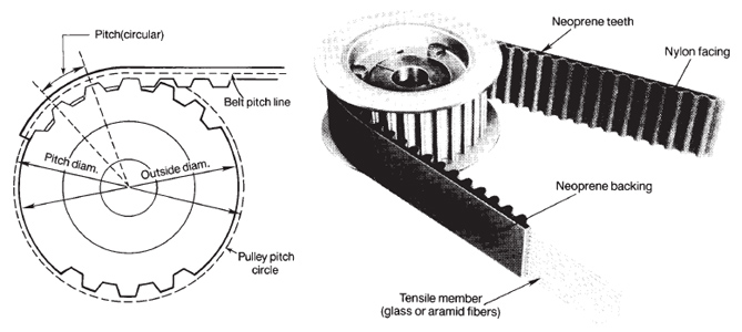
Cog belt (as shown here, click for a larger view) is used on large Whipple, Kobelco, 14-71 &c. fuel cars, but the pulleys and belts are very expensive except where the size is used commercially as in cam drives. Speed accuracy is absolute except that overload, overspeed or inadequate tension will “skip” |
|
|
the belt, and damage or break it. Proper tension is essential, and will be considerably higher than chain drive. Both toothed belts and chains engage by means of teeth, but chain’s back tension is only 1/75 that of toothed belts (from Tsubaki’s “The Complete Guide to Chain”). |
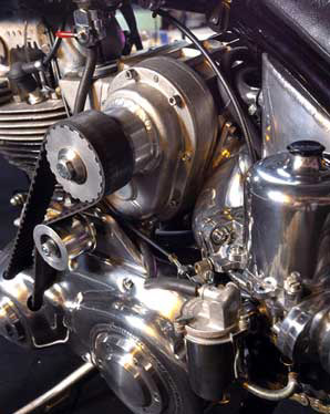
Alignment is more important than with chain drive, and frequently flanged pulleys are used. Commercial supercharger drives are generally much too wide; about 20 to 30mm is about what is needed. Here’s a Norton Atlas with a cog belt drive from the engine sprocket, click for a larger view. |
|
|
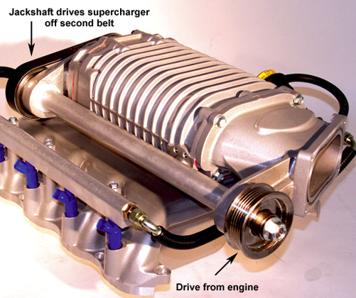
Serpentine or ribbed belt, as used on OEM supercharger drives such as Ford, GM, Jaguar, Mercedes, Mini Cooper, &c. as well as the accessory drive on most automobiles works well, but needs more tension than a cog type, and pulleys and belts are expensive. Both 6 rib and 8 rib are good. Ford Lightning truck lower pulley sizes, which are available from Ford dealers, breakers, jumbles, yards, &c. may be useful for Eaton applications. The stock Ford Lightning supercharger (driven) pulley is 2.83” OD, the engine (drive) pulley is about 7.50” OD. The Ford retro-fit engine pulley numbers are given in added boost in psi vs. the original pulley size.
+2 psi boost lower (drive) pulley = 7.90” OD
+3 psi boost lower (drive) pulley = 8.17” OD
+4 psi boost lower (drive) pulley = 8.50” OD
+5 psi boost lower (drive) pulley = 8.75” OD
+6 psi boost lower (drive) pulley = 9.00” OD.
V belt has been used in various widths and both single and multi-row, and has more power transmission capacity per inch of belt width than a cog type, but requires more pre-load tension (but less than serpentine belt). V belt drive offers some advantages:
» Easy and economical installation
» No lubrication required, runs dry
» Clean & low maintenance
» Elasticity of belts helps shock load dampening
» Quiet, smooth operation
» Long life expectancy
» Good mechanical efficiency (but lower than chain at 96%)
» Narrow and light “package”
Automotive and commercial pulleys and belts can be used or adapted, but watch the manufacturer’s recommendations as to load, tension, maximum RPM and speed in feet per minute.
Flat belt is not really practical due to width and tension requirements, but it will operate on a very small pulley, and at very high belt speed in f/m. Efficiency is very high at 98%.
Gear
This is slightly less efficient than chain and has similar and difficult lubrication requirements. Alignment and pitch spacing is critical, requiring a gear box or similar device to be adapted or constructed rather than free-standing gears. Ratio changes are very difficult. |
Direct
This drives the supercharger off the end of an engine shaft using a coupler, either at engine speed or through a gearbox at a proportion of engine speed. The extreme length makes this impractical, although the efficiency is high. Potvin and Moon made front mount direct drives for the GMC superchargers 50 years ago. Many pre-War British |
| |
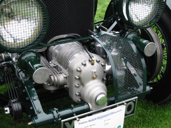
and European factory-supercharged automobiles were direct-driven including Bentley, as shown here, click for a larger view. |
Drive ratio
Once the type and capacity of the supercharger have been selected, the relative speed at which the engine will drive the supercharger must be tested to detect gross mis-matches:
If the supercharger capacity is too small, this requires excessive supercharger RPM either above the safe limit (which will vary with individual models and types), or not practical for the drive method chosen (sprocket or pulley too large or small). Insufficient capacity also means that the supercharger is a restriction in the intake flow path until critical RPM is reached, where its capacity matches the engine’s demand. Below this point power will be less than in normally aspirated mode, both due to restricted breathing and of course the drive load.
If the supercharger capacity is too large, this permits internal leakage reducing boost at low RPM, inefficient operation, and high power loss, or not practical for the drive method chosen (sprocket or pulley too large or small).
There is a rough method of approximating how fast the supercharger must turn in relation to engine speed. It does not include such factors as supercharger wear, the engine’s volumetric efficiency, intake restrictions, &c. and therefore is only useful as an estimator. To calculate the drive ratio to produce the boost desired with the supercharger selected, where:
R: drive ratio (supercharger RPM ÷ engine RPM).
C: engine displacement, either in cubic centimeters, liters ÷ 1,000, or cubic inches × 16.387.
B: boost, in pounds per square inch (psi).
A: atmospheric pressure, in pounds per square inch (psi); 14.7 is approximately correct for sea
level and 70° F. Click for a Table of amospheric pressure at higher elevations: ). Please
note that RAD is preferred to actual pressure when calculating the effects of air conditions on tuning.
V: supercharger volume in either in cubic centimeters, liters ÷ 1,000, or cubic inches × 16.387
per revolution; Roots volume is “displacement”, eccentric vane volume is “swept volume”.
O: Cam overlap; subtract 30 from the overlap in degrees, then multiply by 1% (.01). E.g. for 65°
overlap, O = 65 - 30 = 35, × 1% = .35.
|
R |
|
= |
|
C × (B + O + A)
 |
|
= |
|
Crankshaft pulley OD
|
|
= |
|
Supercharger RPM
|
V × 2 × A |
Supercharger pulley OD |
Crankshaft RPM |
Supercharger capacity vs. supercharger RPM
Where there is a choice between, e.g., an Eaton M62 driven at 100% of engine speed and an Eaton M90 driven at a lower percentage of engine speed (62” ÷ 90” = 68.9% in this case) with both delivering the same capacity, the larger supercharger is preferred despite minor loss of boost at lower speeds due to leakage.
For example, an M62 supplies 62” of intake charge at 100% of engine speed. An M90 will supply the same 62” of intake charge, but at a lower RPM, which is the inverse of the size proportion: 62 ÷ 90 = .689 × 90” = 62”.
Doesn’t this make the choice even - the same volume is supplied in both cases? No, because although the intake charge volume delivered is directly proportionate to the supercharger capacity, the power required to drive the rotors rises as the cube of the supercharger’s driven RPM. To compare the two examples:
1. Multiply the M62 capacity by its RPM to deliver 62” of intake charge at 100% of engine speed:
62 × (1.00)^3 = 62.
2. Multiply the M90 capacity by its RPM to deliver 62” of intake charge at 68.9% of engine speed:
90 × (.689)^3 = 29.4.
The M90 requires only 47.4% as much power (29.4 ÷ 62 = 47.4%) at the lower RPM, about 52% less parasitic loss. This is not only power available to accelerate the motorcycle, but reduced load on the supercharger’s drive mechanism. In addition the extra power raises the temperature of the intake charge, which both reduces engine power and reduces the knock threshold. However, the M62 boost pressure will rise more quickly with RPM. In addition, there is a size, weight and inertial lag disadvantage for the M90 but these are minor considerations by comparison.
To make a valid comparative estimate, find the capacity and required drive ratio for each choice to deliver the correct volume and boost pressure as described above. Multiply the supercharger capacity of each choice times its driven RPM, then divide the result by the supercharger capacity of each choice times the cube of its drive ratio; remove one power (exponent) of each from the proportion to make the math easier: divide the capacity of the smaller supercharger by the capacity of the larger supercharger, and square the result - this is the ratio of power loss between the two choices. 62 ÷ 90 = .689; .689^2 = .474, or 47.4% as calculated above.
Power loss comparisons are only even partially effective when made between models which differ exclusively in supercharger capacity - not between manufacturers (Shorrock vs. Judson), design types (Eaton vs. Arnott), or versions (Eaton Gen. II· vs. Gen. V·), &c.
|
Sample drive ratio calculations:
Example 1, a 750cc engine with 70° of overlap, where 10 psi of boost is required using an Eaton M24 supercharger:
C = 750cc engine displacement
B = 10 psi boost required
V = 393cc supercharger capacity
A = 14.7 psi
O = 70° cam overlap - 30 = 40, × 1% = .4 |
R |
|
= |
|
750 × (14.7 + 10 + .4)
|
|
= |
|
1.63:1 (overdrive) ratio |
393 × 2 × 14.7 |
The supercharger turns 163% of the engine RPM, typical where the supercharger is fairly small, but safe at high RPM. This is a good choice, since the supercharger is very small and its RPM at this drive ratio with the engine at 8,000 RPM is 13,000, well below Eaton’s limit of 15,000. |
Example 2, a 1,000cc engine with 80° of overlap, where 20 psi of boost is required using a Wade RO20 supercharger:
C = 1,000cc engine displacement
B = 20 psi boost required
V = 2,000cc supercharger capacity
A = 13 psi (high elevation)
O = 80° cam overlap - 30 = 50, × 1% = .5 |
R |
|
= |
|
1,000 × (13 + 20 + .5)
|
|
= |
|
.64:1 (underdrive) ratio |
2,000 × 2 × 13 |
The supercharger turns 64% of the engine RPM, typical where the supercharger is much larger than the engine, and also has limited maximum RPM. The lower atmospheric pressure (13 vs. 14.7 psi) requires a bit more work from the supercharger, but also recovers all the power normally lost by the thinner air. |
Example 3, a 500cc engine with 60° of overlap, where 30 psi of boost is required using a Shorrock C75 supercharger:
C = 500cc engine displacement
B = 30 psi boost required
V = 750cc supercharger capacity
A = 14.7 psi
O = 60° cam overlap - 30 = 30, × 1% = .3 |
R |
|
= |
|
500 × (14.7 + 30 + .3)
|
|
= |
|
|
1.02:1 (overdrive) ratio |
750 × 2 × 14.7 |
The supercharger turns 102% of the engine RPM, typical where the supercharger is large, and also has limited maximum RPM. |
Example 4, a 828cc engine with 75° of overlap, where 20 psi of boost is required using an Eaton M45 supercharger:
C = 828cc engine displacement
B = 20 psi boost required
V = 737cc supercharger capacity
A = 14.7 psi
O = 75° cam overlap - 30 = 45, × 1% = .45 |
R |
|
= |
|
828 × (14.7 + 20 + .45)
|
|
= |
|
1.34:1 (overdrive) ratio |
737 × 2 × 14.7 |
The supercharger turns 134% of the engine RPM, typical where the supercharger is moderate size. This is not the only choice, but good because the drive ratio does not require extreme sprocket sizes, and its RPM at this drive ratio with the engine at 7,000 RPM is 9,380, well below Eaton’s limit of 14,000. |
Example 5, a 750cc engine with 70° of overlap, where 10 psi of boost is required using a B&M supercharger (a miniature GMC Roots variant at 2,360cc):
C = 750cc engine displacement
B = 10 psi boost required
V = 2,360cc supercharger capacity
A = 14.7 psi
O = 70° cam overlap - 30 = 40, × 1% = .4 |
R |
|
= |
|
750 × (14.7 + 10 + .4)
|
|
= |
|
.27:1 (underdrive) ratio |
2,360 × 2 × 14.7 |
This is the poster child for poor choice. The supercharger is so large (although small for an automotive unit) that its drive ratio must be slowed down to almost 1:4 (.27:1). At that speed air leakage around the rotors is very high, and low speed performance will be worse than stock due to the high drive load. Think of this when someone remarks that “my friend built a BSA with a GMC 6-71 blower on it”. No, he didn’t. |
Boost estimation
The same formula may be inverted to estimate the boost produced by a specific combination of engine size, supercharger capacity and drive ratio. The same terms apply: |
B |
|
= |
|
R × V × 2 × A
|
|
- (O + A) |
C |
Example A, a 750cc engine with 70° of overlap, with an Eaton M24 supercharger driven at 2.00:1 ratio (200% of engine speed):
C = 750cc engine displacement
R = 2.00:1 ratio
V = 393cc supercharger capacity
A = 14.7 psi
O = 70° cam overlap - 30 = 40, × 1% = .4 |
B |
|
= |
|
2.00 × 393 × 2 × 14.7
|
|
- (.4 + 14.7) | |
= |
|
15.7 psi |
750 |
Safety
Despite careful planning, boost pressure may exceed expectations, which stresses all components and connections between the compressor discharge and the intake valve; hoses may pop-off, threads strip, walls of sheet-metal plenums burst, &c. In addition, a backfire caused by ignition malfunction &c. has even greater capacity for destruction.
The plenum or any components large enough to be practical may be protected by a safety pop-off valve. This is not the same as a blow-off valve intended to regulate excess pressure by venting it on a continuous basis, and may be easily constructed out of common material at minimal expense. Since this is EFI, only hot air is vented and shouldn’t disturb anything, so no duct is needed.
A simple cover plate, loaded in place with a calculated valve spring and installed with gasket sealer (after all, it's a safety device not a regulator) will cost perhaps $10.00.
For vent size I suggest 4 × 1.5” holes (7.1 sq.” area) made with with a hole saw and neatly deburred & radiused, covered with a 6” × 6” × 1/4” thick rectangular aluminum plate across the top.
A 3/8” hole centered between the vents, with a high quality 3/8” bolt inserted from below through the roof (or your choice) of the plenum with a thick big diameter washer under the head (pin the bolt in place, or make sure you can reach it from inside). The bolt goes up through cover plate by 2”, and is secured and adjusted by a Ny-Loc nut and valve spring collar. The local pressure on the 7.1” area should your maximum boost + 5 psi. E.g., 20 psi expected, 25 psi × 7.1” area: the cover plate will pick up against 176 lbs. of spring tension, but just barely.
Remember, just cracked open may not vent excess boost as fast as the compressor is supplying it, so don’t assume a pressure drop is a done deal.
A big triple valve spring (used is fine) should be sufficient. Test with an air compressor for cracking pressure. It may need to lift 1/2” to vent everything, so a big spring is needed.
For more vent area, use bigger holes or more holes; 2 springs will probably be better here.
If this is a draw-through carbureted system, the plenum contents are flammable, and must exhaust only into a safe duct, and pass outside the vehicle without going near exhaust, electric, operator, &c. |
See these Victory Library booklets |

|

|

|

|

|

|

|

|

|

|
|
|