|
|
 |
Toyota 3MZ-FE V6 Engine
Performance modifications |
Here I will make various observations and comments on how the 3MZ-FE engine, transmission &c. function, and in some cases how to make improvements. New material will be added regularly, and eventually better organized. Click below to jump directly to an individual topic. |
Engine systems operation
The 3MZ-FE engine is available in some Toyota Camry, Avalon, Solara, and Lexus among others. It’s related to the earlier 1MZ and 2MZ.
Toyota “MZ” series engines |
Engine | Bore | Stroke | Displacement |
1MZ | 87.5mm | 3.445” | 83mm | 3.268” | 2,995cc | 182.7” |
3MZ | 92mm | 3.622” | 3,311cc | 202.0” |
2MZ | 87.5mm | 3.445” | 69.2mm | 2.724” | 2,497cc | 152.4” |
3/2MZ hybrid | 92mm | 3.622” | 2,760cc | 168.4” |
The static (nominal) compression ratio is 10.8:1 which gives good mileage and power, but will be knock-limited by even mild supercharging or nitrous use.
The Toyota alpha-numeric engine designator codes mean: |
“3” | 3rd generation (2003-2006) |
“MZ” | the engine series, a conventional 60° V bank angle design V6, with both the block and heads in aluminum alloy, and belt-driven DOHC (double overhead camshaft) |
“F” | “economy” twin cam head with a relatively shallow valve angle of 22.5° for a compact and thermally efficient combustion chamber (“G” is the “performance” twin cam head design, with a wider valve angle) |
“E” | electronic fuel injection |
Here’s a link to the Wikipedia article:  |
Crankshaft design
The “natural” firing order and cylinder separation of a V6 is at 120° intervals; this produces a power stroke evenly every 1/3 of an engine revolution.
Some V6 engines have their opposing cylinders (1&2, 3&4, 5&6) on the same crankpin or rod journal, and their separation is exactly the same as their bank angle: 60°. This is inexpensive to build, but not very smooth and impossible to balance perfectly.
A 120° bank angle V6 with common (shared) rod journals for opposing cylinders is also inexpensive to build, and better balanced, but is too wide to fit in the FWD engine bay. |
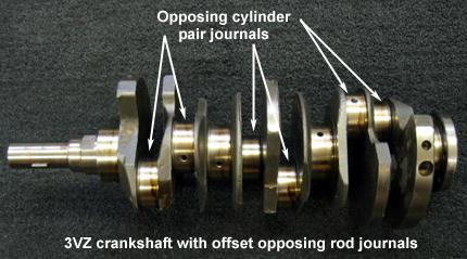
Toyota has combined the 60° bank angle to keep the engine narrow, and added 60° to the firing order for a total of 120° by “offsetting” the opposing crankpins. This is far more expensive, but produces superior results. The crankshaft resembles an inline 6 cylinder except that there are only 4 main bearings like most other V6 engines (a modern V8 has 5 main bearings, a modern I-6 has 7). Shown is the older but similar Toyota 3VZ crankshaft; click for a larger view. |
|
|
Strength limits to more power
The forged steel crankshaft is fairly robust, with 53mm (2.087”) rod journal diameter and 61mm (2.402”) main journal diameter. The nominal journal overlap is 15.5mm (.610”). Some major components (block, crankshaft, bearings, 6 bolt main caps, cam drive system, oil pump) appear strong enough to withstand perhaps 600 hp and 7,000 RPM without modification. However, the cast pistons, connecting rods, valve springs, will need replacement. Click here to read more about building a serious 1MZ engine:
The crankshaft could be stroked by welding and regrinding in the traditional manner. The usual increment is 6mm (about 1/4”), giving 89mm (3.504”) for 3,550cc. This will be very expensive since the engine has 6 rod journals, vs. 3 paired journals in most V6 engines, and 4 paired journals in V8 engines which are welded and ground as a single journal. In my opinion this is not a practical field of endeavor. |
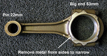
The connecting rods are not as robust as we may wish, but substitution of a rod from another engine is limited by the large journal size. However, the Toyota 1981-95 20/22R 4 cylinder SOHC rod is a stronger design, with suitable length (5.83” or 148mm is approximately stock), with the same 22mm (.630”) piston pin |
|
|
diameter and the same 56mm (2.205”) big end ID. The later 3RZ rod appears to be the same but 147mm long.
The 22R rod is too wide across the big end at 22mm (.866”), and must be narrowed by precision grinding from each side by 3mm to the same 16mm (.630”) width as the MZ rod (plus whatever additional side clearance the engine builder suggests). Shown, above right, is a stock 22R rod which is available new and used. In my opinion, the stock 22R rod rebuilt with ARP bolts is strong enough for all but the most severe use. Click the picture for a larger view. |
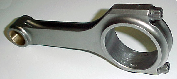
Various aftermarket suppliers including Eagle, Pauter, Crower etc. make 22R rods (but not MZ rods as of today). Obviously, you need 1½ sets. Eagle #5819T3D in the popular “H-beam” style (about $80. each) are shown, right. Click the picture for a larger view. | |
|
Throttle body spacer
These fine products are a snare for the unwary, and do nothing (unless you count telling the guy on the next bar stool about it).
The “tests” referred to in the ads and favorable comments somehow forget to explain how more air goes through a hole if it’s longer. The reason: it doesn’t.
Among the claims: |
| » | “More torque”? Sure - if the airflow volume is lowered (by reducing the X-section area with those cute little vanes), producing more velocity, but this reduces peak power. Ooppssss.....
| » | “More power” read above.
| » | These things were “invented” about 100 years ago, and sold to half of the Model T owners. J. C. Whitney sold one to your great-grandfather 75 years ago... and he threw it away.
| » | “produces air breakup”?
Really - how does air break up? Isn’t it still molecules of oxygen etc?
| » | “produces turbulence”?
Yes it does, but this violates the first rule of port efficiency: no turbulence - as close to laminar as possible. The air does something quite different as it passes through the valve seat in any case. | | | | |
Please note: no patent is claimed. Why is that? Here’s the response they got back from the patent office: HAHAHAHAHAHAHAHA
Then why does everyone say it works? Because: |
| 1. | it’s expensive ($cience!!!) - if it cost what it should ($15.00 - it’s a piece of metal with a hole in it) no one would believe it works.
2. | the alternative is to admit “I wasted $300 for this?”.
3. | “heat-treated T-6061 aircraft quality solid-billet aluminum”. That sounds really nice, but it has nothing to do with the claims - it makes no more sense than a titanium + carbon fiber tissue dispenser for the dashboard. | | |
It would work exactly as well (i.e., not at all) if carefully crafted from a block of stale cheese. |
Some of what is claimed and posted about cold air and ram air intakes is complete rubbish. In general, there are a few things that may help:
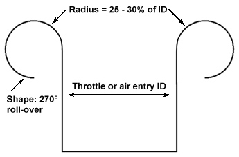
If the new tube has a larger bend radius and/or diameter than original ducting this will increase air volume slightly. The end of the intake (inside the filter) should be a 270° rolled-over radiused lip, not cut off flush. The radius should be 25 to 30% of the diameter (although the gains beyond 3/8” are minimal). For example: if the entry is 70mm to match the TB, the radius should be at least 17.5mm or .69”. None that I’ve seen are big enough. The difference in flow between a good shape and a bad one is over 5%. Click the picture for a larger view. |
|
 |
|
The tube (and the entire tract) must have a smooth interior wall - the bendible, conformable flex tubes are completely worthless - the spiral or corrugated inner wall drastically reduces air-flow.
Aluminum is almost the worst material for the tube (silver or copper would be worse) because it transfers heat too quickly. Steel tubing polished, plated, or painted silver is much better, the weight difference is only a few ounces. ABS such as used for DWV (available in many large sizes inexpensively at Home Depot, &c.) is useful here also since it’s a good insulator and the interior walls are very smooth. It can be constructed in sections using standard commercial shapes (45° bend, U bend, etc.), glued together and painted.
If the new filter area is larger than the OEM this increases flow slightly - but this is not always an accurate comparison, since not all filters flow the same per square inch of area.
A filter re-located to anywhere inside the engine compartment gets only pre-heated air from the engine (unless masked with an enclosure, &c.). Under WOT the heat throw-off from the exhaust and hot air pulled through the radiator by the fan is huge. A CAI located in the engine bay is in the “prop wash” of the radiator, and will getting 180+° F air continuously by convection. Air is also not an insulator to heating by radiation - luckily, this is minimal except at very low speeds.
The biggest power boost you can get from the intake duct is cold air - the difference between 70° ambient air from in front of the car vs. 150° or more taken from inside the bay is large. Ideally, an intake should have a remote tube ending outside the engine bay in front of the bodywork (grill, under bumper, &c.), and a water trap to prevent rain and road dirt from reaching the filter.
The duct from the entry need not be a continuous diameter, or even a continuous cross-section (as long as the minimum area is substantial). It can end in a big box containing the filter, then another tube back to the throttle body.
Pointing an external intake scoop forward does not produce enough “free supercharging” to make much difference, the dynamic (wind) pressure is only about 1.2% at 100 mph.
Even a K&N filter has to be big enough to work; for example: a 3.3 liter engine peaking at 6,000 RPM needs about 47 square inches of filter to work (6” × 8” panel, &c.). The K&N formula for filter surface area: (engine size in liters × RPM ÷ 418). 3.31 liters × 6,000 RPM = 19,800, ÷ 418 = 47.4 square inches. The K&N replacement filter for the 3MZ is 5-7/8” × 11” for 64.6 square inches, or sufficient for 8,000 RPM.
When you remove the original stuff (especially the resonators), you get a bit more intake roar (sounds nice, though!), but it cancels any benefits from the original tuned intake system; see above: . |
Throttle body
The original TB is 70mm (2.75”) inside diameter, which is more than adequate for the stock, or even a mildly modified engine. With test conditions of 95% VE, ambient air 29.92” Hg @ 75° intake temperature, 5,800 RPM peak power the 70mm TB produces a pressure loss at the manifold of only .219 psi (.446” Hg).
Substitution of a larger 75mm TB, widely touted as a power mod,
reduces the loss to .164 psi (.333” Hg), but is only worth about ½ HP, and that at only at high RPM and full throttle. |
As reported by Stefan Vince, SAE: “a TB increase will change the resonant RPM of the intake. It’s the same as enlarging the neck diameter on a Helmholtz resonator. That change may provide the bulk of any power increase seen at higher RPMs. The effect on the resonating system must be considered for any TB change on a plenum type intake. The OEMs’ use of large TB size is normally to reduce pumping losses.” Click the logo to visit Stefan Vince’s “Performance Engine Components’s web site. |
|
|
|
Here’s a rough guide to selecting a throttle body by minimum intake pressure loss. Please note: do not use these pressure drops to determine carburetor size, where losses below .25 psi are not suitable for anything but race engines, and .75 psi for high performance. |
Intake pressure loss guidelines |
Psi | In., Hg | Application |
1.473 psi | 3.000”Std. CFM rating for 1 or 2 bbl. carburetor | |
1.000 psi | 2.036” | safe for any use, mild peak power loss |
.737 psi | 1.500”Std. CFM rating for 4 bbl. carburetor | |
.500 psi | 1.018”high performance, leaves little power on the table | |
.200 psi | .407”slight power increase, delicate throttle operation or modified controls suggested | |
.100 psi | .204”race only, not suited for daily driver and traffic | |
Later models with “drive by wire” (electronic) throttle control cannot substitute a cable or linkage-controlled TB directly, since the control signal affects other computer functions.
Click here for comments on modifying older conventional TB linkage for better control: .
The optimum duct size to supply a throttle body is 25% larger than the TB’s area. The transition from the duct ID to the (smaller) throttle body ID is a radius, for which the formula is: R/D=.5, where “R” is the desired radius, and “D” is the throttle body diameter. This radius combined with 25% larger area leading to the throttle body reduces the velocity to exert more pressure on the throttle body. Here are some TB diameters vs. intake diameters: |
Throttle body diameter vs. air inlet diameter |
TB | 56mm | 58mm | 60mm | 62mm | 64mm | 66mm | 68mm | 70mm | 72mm | 74mm | 76mm | 78mm | 80mm |
Radius | 28mm | 29mm | 30mm | 31mm | 32mm | 33mm | 34mm | 35mm | 36mm | 37mm | 38mm | 39mm | 40mm |
Duct | 63mm | 65mm | 67mm | 69mm | 72mm | 74mm | 76mm | 78mm | 80mm | 83mm | 85mm | 87mm | 89mm |
TRD supercharger
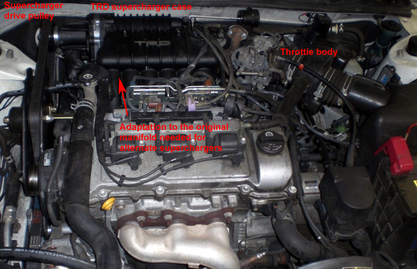
The TRD supercharger kit, designed and manufactured by Magnuson Products from the basic Eaton M62 Generation IV· supercharger, was only available for the earlier 1MZ-FE engine. With the original drive pulley size, it produced 5 psi in the 3.0 liter engine, but required about 35 hp to drive it. The outlet (compressor discharge) temperature is increased 50-60° F over inlet temperature. If the drive ratio is increased to 2.5:1 (supercharger 15,000 RPM, engine 6,000 RPM) it will produce 10 psi. It has been discontinued and is now hard to find.
Here’s a picture showing a TRD 1MZ-FE installation by Solaraguy.com member ndeguzma. Click on the picture for a larger view; click here for the Solaraguy.com thread and more details: |
|
|
| |
5 speed automatic transmission
This has overdrive (indirect) final gear, which lowers engine speed in 5th for reduced wear, noise &c. and increased gas mileage. Using the original P215/60R16 tires (26.16” tall), the internal ratios are:
|
Gear ratios | RPM lost | RPM
recovered | RPM after shift | Overall
ratio | Speed per
1,000 RPM | Speed in gears
@ shift RPM |
1st | 4.235:1 | Shift out of 1st at 5,800 | 13.94:1 | 6 Mph | 32 Mph |
2nd | 2.360:1 | -44.3% | 55.7% | into 2nd at 3,232 | 7.77:1 | 10 Mph | 58 Mph |
3rd | 1.517:1 | -35.7% | 64.3% | into 3rd at 3,728 | 4.99:1 | 16 Mph | 90 Mph |
4th | 1.047:1 | -31.0% | 69.0% | into 4th at 4,003 | 3.45:1 | 23 Mph | 131 Mph |
5th | .756:1 | -27.8% | 72.2% | into 5th at 4,188 | 2.49:1 | 31 Mph | 181 Mph |
|
It is readily apparent from the table that the nominal top speed of 130 mph is limited by engine power, not by RPM. At 130 Mph the engine is only turning about 4,150 RPM and in fact the top speed might actually be increased by raising the axle ratio from 3.291:1 to perhaps 3.500:1, which would raise the engine speed to 4,420 RPM - closer to its rated power RPM. Don’t have a U151E? Find your own ratios here:
All modern automatic transmissions have torque converters, and all torque converters have stall (maximum engine speed before the engine stalls or the car moves), there is no such thing as a “stall converter”. Engines built for increased power with radical cams suffer from reduced low speed power, and a converter with increased stall speed allows the engine to spin faster for a better launch. The increase can be done by either changing the angle, diameter or pattern of the fins, or reducing the diameter of the shell (outer body), or any combination of these.
There is a practical limit to this, since all FWD cars have weight transfer from the drive wheels on launch - if you have too much power or too much stall speed, you simply spin the tires.
Converters prepared for serious use (blower, nitrous) frequently have their fins, which are commonly crimped to the torus shell, brazed in place to prevent them from “laying over” (bending) from hydraulic pressure under severe load - expect to spend money on this.
In addition to the 1st gear torque multiplication, the torque converter also multiplies engine torque by perhaps a factor of 1.9:1 for the first few feet until the stator spins up to speed. This gives a brief but effective overall 1st gear ratio of about 8:1.
The U151E works well with the stock engine, but needs some modification when the engine is supercharged. These changes include:
» modified valve body calibration to improve shift quality
» additional friction clutches for more surface area
» internal oil passages ported and enlarged for better cooling and faster application of fluid pressure
» pressure regulator boost valve modified for response time
» generally, the line pressure is raised to apply more force to the clutches
» for sustained boost more transmission cooling capacity is needed, usually by adding a remote
radiator in series. |

See these Victory Library booklets |

|

|

|

|

|

|

|

|

|

|
|
GMC, supercharger, blower, 6-71, 671, 8-71, 871, pressure, adapt, convert, manifold
|