|
|  |
Here I will make various observations and comments on how the drum brakes function, and in some cases how to diagnose minor faults and make improvements. New material will be added regularly, and eventually better organized. Click below to jump directly to an individual topic. |
Drum brake function
Drum brakes are original equipment on all older motorcycles including factory racers. However, there are differences in design efficiency that cause the larger and better drum systems to work as well as disc brakes under all but the most demanding conditions, while retaining “classic” and “period” appearance. In some cases, rules limit vintage racers to contemporary brake designs.
The important drum brake components for one wheel are:
» one (or two) drum(s): cast-iron, steel or stamped sheet metal friction (inner contact) surface
within a cast-iron, steel, aluminum or magnesium body
» two (or two pair of) curved shoes: cast-iron, steel, stamped sheet metal, aluminum/zinc or
magnesium alloy
» two (or two pair of) curved brake linings: friction material bonded or rivetted to the shoes
» two (or two pairs of) return springs
» one (sometimes two or four) eccentric cam(s): steel, cast-iron or aluminum alloy
» one (sometimes none, sometimes two or four) anchor post(s): steel, cast-iron or aluminum alloy
Drum brakes convert the wheel’s rotational inertia (kinetic energy) to heat (thermal energy) by pressing the brake lining material against the inside surface of the drum. The resultant friction increases the temperature of both the lining and the drum, and is transferred from the drum’s exterior surface to the atmosphere by radiation (at all speeds) and convection (which increases with vehicle speed).
Front vs. rear brake
The relative effect of the front vs. rear brakes was not understood for many decades, and cautionary messages to avoid use of the front brake were common. It is now realized that the front brake does almost all the work; at least 75% and as much as 90% depending on the wheelbase, weight distribution, tire size, speed &c. Original rear drum brakes are frequently sufficient in type, size and mechanical advantage for competition purposes, although a change in lining material may prove helpful, and additional cooling for sustained use.
Under braking, weight transfers forward, which relieves the rear wheel of most weight, reducing rear wheel traction. This is not due entirely to front suspension compression, &c. (although this a contributing factor) and takes place even in rigid frames with no suspension travel. Shorter wheelbase machines with high centers of gravity have greater weight transfer. The front wheel now has increased traction, and can accept much more braking force before its traction limit is reached. All but the most advanced front drum brakes are inadequate for performance use, and even these can be improved to some extent.
|
Brake shoe types |
The “primary” or “leading” shoe (always present) is applied in the direction of drum rotation by the rotation of the brake cam, which “wedges” the leading edge of the shoe against the drum surface. The friction is the total of the wedging action, plus the leverage and pressure of the cam. In addition to increased pressure, this also has a self-energizing “servo” effect in that the primary shoe is more tightly wedged in place by drum rotation without additional cam movement, so its effect increases automatically without any change in cam or hand-lever motion. The amount of torque contributed by a leading shoe has been calculated as 27.9% higher than that of a trailing shoe, so the proportionate effect of the primary shoe vs. the secondary shoe is roughly 56% vs. 44%. |
The “secondary” or “trailing” shoe (only present in single leading shoe systems, also called “1LS” or “SLS”) is applied against the direction of drum rotation by the rotation of the brake cam, which forces it against the drum surface. The friction (and heat transfer, and effectiveness) is limited by the leverage and pressure of the cam. This system works equally well in either direction, and therefore prevents “roll-back”. | |
|
“2-SLS”, or twin single leading shoe, is a variant of this type using a hub with two drums back to back, and one mirror-image backing plate with conventional SLS shoes on either side. A Grimeca 180mm 2-SLS is shown here, right. Notice the single cam lever, and no linkage. Click the picture for a larger view. |
A dual leading shoe system (also called “2LS” or “DLS”, or “4LS” when two siamese drums per wheel are used) substitutes another primary shoe and its cam &c. for the existing secondary shoe. This increases the braking force by about 14% (½ of the 27.9% higher effectiveness of the extra primary shoe, since only one shoe is being changed). This makes for lighter but more delicate control. A dual leading | |
|
shoe system only works in the designed direction, and is almost useless when reversed.
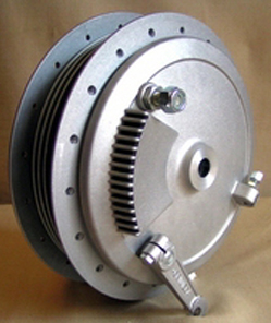
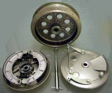
Grimeca 230mm 4LS components are shown here, right. Notice the two cam levers, with connecting linkage. The 2nd backing plate is not shown, but would be a mirror image of the one in the right foreground, and visible through the drum holes. Click the picture for a larger view.
A 4LS system does not offer any advantage in operation compared to a 2LS system with the same total lining area, and in fact carries the important penalties of extra weight, complexity of assembly and adjustment, and reduced options of cooling and mounting.
However, the “flare” or “bell-mouth” (heat-induced taper expansion of the drum’s unsupported open end) is reduced since the outer end of each drum is substantially closer to the drum’s inner surface, and is more stable under severe use.
A 4LS system also applies brake torque back into both sides of the front fork equally (rather than loading only one leg, which may cause stanchion binding and misalignment). |
Movement vs. effort
Except for the “wedging” effect of the primary shoes(s), shoe application pressure to the drum surface is directly proportionate to the hand-lever effort, but inversely proportionate to the shoe application distance (viz. how far the shoe must move to make contact), and is determined by the ratios of the intermediate components, as follows:
1. the brake hand-lever length to its pivot bolt ÷ by the distance from the cable ferrule to the pivot bolt is the hand-lever’s mechanical advantage (handle movement distance × effort = cable movement distance × pull at the cam lever on the backing plate, &c.).
2. the brake lever length at the backing plate from the cable clevis hole to the lever pivot ÷ the lever length from the lever pivot to the cam is the brake lever’s mechanical advantage. The brake lever multiplies the mechanical advantage of the cable. In general, only 2LS and 4LS brakes have this lever type; single leading shoe types typically have only a single lever operating the cam directly from the cable. The presence of linkage (rather than a single arm) on the backing plate is a reliable indicator of a dual leading shoe system.
3. the cam lever length from the pivot to the cam ÷ the cam’s eccentric motion (the height of the cam lobe) is the cam’s mechanical advantage.
There is no arrangement or combination of parts that gives lighter hand pressure with the same effort applied to the shoes, or the same hand pressure with stronger shoe application. Every choice of components and sizes is a compromise, whether operated by cable, lever, bell-crank, hydraulic cylinder, or any combination of these. Greatest efficiency will derive from the most rigid parts, reducing all flex and slack, and proper lubrication.
Any of these dimensions can be changed, and will have an effect on the effort vs. movement ratio directly proportionate to the ratio of new ÷ old. Adding 10% to the length of the lever-to-cable length increases tension on the shoes by 10%, but requires 10% more movement at the handle, &c.
In terms of response to the movement of the hand lever and the rider’s effort, a hydraulic disc is completely “linear”: more effort = more stopping power in a 1:1 ratio. There are no ranges or periods of different effectiveness. A lightly applied disc brake will stop the machine in much the same way as coasting to a halt.
A single leading shoe system (SLS or 2-SLS) has some initial servo action, where the brake will self-energize to a higher application pressure without any effort by the rider.
A dual leading shoe system (2LS or 4LS) has even stronger servo action, causing some inexperienced riders to lock the wheel up inadventently. The brake feels “nervous” compared to a disc or SLS system. However, it does lessen the amount of effort required for stopping, making it a possible choice for small hands, &c. Both SLS and 2LS brakes will lock the wheel as the machine rolls to a halt, and must be partially released at the last moment to provide a smooth stop. |
Here’s a comparison of the features and function of the most common drum brakes. |
Table 1: Relative effect of drum brake systems |
Term | Meaning | Drums | Primary (leading) shoes | Secondary (trailing) shoes | Brake torque applied |
SLS | Single leading shoe | 1 | 1 | 1 | one fork leg |
2LS | Dual leading shoe | 2 | 0 |
2-SLS | Twin single leading shoe | 2 | 2 | 2 | both fork legs |
4LS | Four leading shoe |
4 | 0 |
2LS linkage operation |
The individual cam levers are normally joined to work simultaneously, although this is not the only method. The connecting link may be of two types:
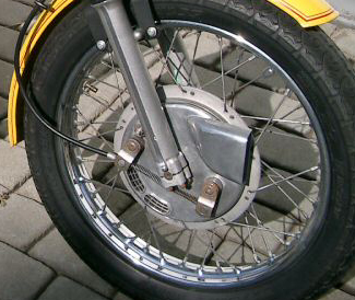
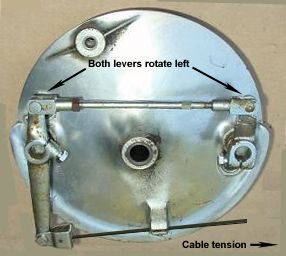
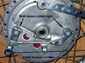
1. cable, which acts directly in tension on both cam levers. This is done by anchoring the cable sheath at one lever, and the cable end at the other lever. The two brake cams pivot in opposite directions against the shoes. When the cable is | |
|
tensioned, both cam levers rotate towards each other in opposite directions with equal tension. No balancing or adjustment is needed since the system is self-correcting in this regard. This method was used by BMW, and by BSA/Triumph on the 1971-72 “conical” front brake (so called because the drum’s outside diameter is tapered, with the cast-iron liner in the larger end), shown here. |
2. rod, which may work either in tension (preferred) or compression. Tension applications are more common. Generally the cable sheath is anchored at the backing plate, the “master” cam lever is lengthened to accept the cable end, and an adjustable rod with heim (rose) or clevis jointed ends connects the two levers at exactly the same distance from the cam centers. The cam levers are on the opposite side of the cams as | |
|
the linkage, and move in the opposite direction to cable tension. Pulling on the master cam lever also pulls the “slave” cam lever. The rod is generally threaded at one end to permit length adjustment to be made by rotating one clevis in ½-turns to synchronize the shoes. The degree of precision of the length adjustment is then determined by the pitch of the rod’s thread: 28 tpi = .036” per turn, .018” per ½-turn, &c. A CB77 Honda “Super Hawk” 305cc 200mm 2LS is shown here. |
In compression applications the same general pattern is followed where the cable sheath is anchored at the backing plate, the master cam lever is lengthened to accept the cable end, &c. However, the cam levers move in the same direction as cable tension, which pulls the master cam lever, which in turn pushes the slave cam lever. The cam levers are on the same side of the cams as the linkage. Com- | |
|
pression applications require more stiffness to the linkage to prevent bowing under pressure, which reduces brake force on the slave cam lever. A Suzuki GT750 200mm 4LS is shown here.
There are also variations where the link crosses through the center of the backing plate, and the cam levers rotate in opposite directions. These choices are not arbitrary, but partially based on backing plate orientation in the fork, presence of an air scoop, speedometer drive, cable run, &c. |
Adjustment
The axle, torque stay (if any) and fork cap bolts should be loosened before the adjustment.
The cable tension must be slacked off to permit completely free movement of all linkage.
The adjustment procedure given in the service manuals for the BSA & Triumph conical brake is accurate and will provide satisfactory results if followed correctly. The individual brake cams must be adjusted separately.
Remove the locating pin or bolt from the link connecting the two cam levers.
Apply both cam levers full on. The shoe application force must be as close to “real world” as possible, not just a light push, to get any “springiness” or compliance out of the linkage etc. Some manuals suggest a wrench or extension bar on the lever to increase mechanical advantage.
Adjust the length of the link until the loose end just fits back into the free cam lever.
Insert the pin and tighten all linkage fasteners.
Remove cable slack to permit only the specified distance between the lever and bracket, &c.
After the brake adjustment is complete the wheel should be rotated rapidly in normal direction, then the brake clamped full on to stop the wheel abruptly.
Re-tighten the fork cap, axle &c. bolts. |
|