|
|  |
Here I will make various observations and comments on how the drum brakes function, and in some cases how to diagnose minor faults and make improvements. New material will be added regularly, and eventually better organized. Click below to jump directly to an individual topic. |
Analysis and modifications: inadequate stopping power
In addition to actual damage, inaccurate adjustment, severe lining wear &c. I’ve seen quite a few “inadequate” 2LS brakes of various brands that on closer inspection turned out to be:
1. aftermarket cable with spongy sheath
2. wrong hand lever
3. mis-routed cable with multiple “S” bends
4. lining very worn with radius much smaller than the drum OD
5. worn cam, bushing or shoe only making partial travel on application
6. drum “cleaned up” by removing rust only on the outer edge of ID, causing partial shoe contact
7. wrong linkage
8. reversed linkage
9. severe wear in the linkage clevis holes causing reduced motion on the slave cam, which converts
2LS to 1LS
All of these owners had examined the brake components carefully, but saw no broken parts hanging by a thread, and therefore assumed the poor results were a design flaw.
The efficiency of a drum brake system can be improved by several methods, among them are:
The cam lever should be positioned on the cam to form an acute angle (less than 90°) to the cable run at rest. On application, the lever passes through a 90° angle to the cable, ending with the complementary obtuse angle (greater than 90°, and equal to 180° minus the “at rest” angle), symmetrically disposed around the 90° point. This gives the largest lever movement and cam rotation for a given cable travel, but I prefer the angle at rest to be somewhat more acute and end at 90° to give the most leverage at the point of shoe contact.
The cable run from the sheath anchor point on the backing plate should use the largest practical radius to reach the perch at the handlebar. In some cases, re-routing the cable, or a longer cable, allows a single more direct large-radius curve instead of multiple complex curves.
The cable should be of large diameter fine multi-strand wire.
The sheath should be thick-walled, and nylon or Teflon lined, otherwise adequately lubricated.
The amount of slack at the handlebar adjuster must be no more than sufficient to prevent the cam from being tensioned when relaxed. If measured carefully even .5mm (.020”) of slack at the adjuster is acceptable but should be inspected regularly. Any additional slack will reduce cam lever travel and brake shoe application pressure.
|
Handlebar levers |
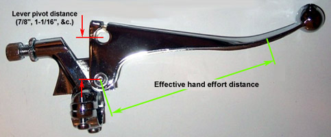
British handlebar brake levers have been made in at least two variants as to the position of the cable barrel receiver hole; there may be others. The “effective” lever length (shown as the green line in the illustration, right) is not to the extreme end of the lever since that isn’t the natural hand position, but rather to a point slightly inboard where |
|
|
the palm of the right hand would end. The ratio of the distance from this point to the lever’s pivot bolt to the distance between the pivot bolt and the cable end (shown as the red line) is the lever’s ratio or mechanical advantage. British levers are available with cable-to-pivot distances of 7/8” (22mm) and 1-1/16” (27mm), and may be interchanged provided the cable fits, slack adjustment is within range, &c. Various Japanese and European levers may interchange with the same caveats. Click on the picture for a larger view.
Substituting the lever with the shorter (7/8”) cable-to-pivot distance for the longer changes the lever’s mechanical advantage by the ratio of 1.0625:.875 for an increase of 21.4%, but decreases the travel distance by 17.6%. This reduces hand effort to this degree, but the shorter cable movement may not apply the brake fully before the lever bottoms out on the grip.
Substituting the lever with the longer (1-1/16”) cable-to-pivot distance for the shorter changes the lever’s mechanical advantage by the inverse ratio of .875:1.0625 for a decrease of 17.6%, and an increase of 21.4% in the travel distance.
There is no lever (or other existing component) that increases cable travel with reduced effort.
The hand-lever must not bottom out against the grip or handlebar when the brake is fully applied. If the lever’s ball end touches the handgrip before full compression, try the lever with the longer cable-to-pivot distance. If the longer hand-lever still bottoms out some part of the mechanism is out of adjustment, bent, loose, or incorrect.
If the hand-lever will not compress completely and the brake is not effective, try the lever with the shorter cable-to-pivot distance. If the shorter hand-lever does not give adequate braking the backing plate cam lever should be lengthened to provide an alternate cable attachment point farther from the cam, or some other alteration or substitution to increase the hand-lever’s mechanical advantage. If the hand-lever will not compress completely (but the brake is effective) no correction is needed, unless the effort is tiring or uncomfortable. |
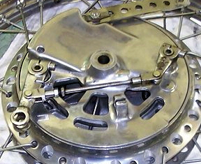
Linkage modification |
The mechanical advantage of a cam lever is proportionate to its length. The length is measured between the cable or link hole and the center of the cam. In some cases, there is sufficient room between the existing cable hole and the end of the lever to drill another hole to increase this distance and reduce hand-lever effort and sensitivity without disassembling the brake, or even (in some cases) removing it from the | |
|
motorcycle. This must have sufficient material between its outer edge and the end of the lever to prevent breakage. The new hole may change the lever’s “clock” position (rotation) on the cam.
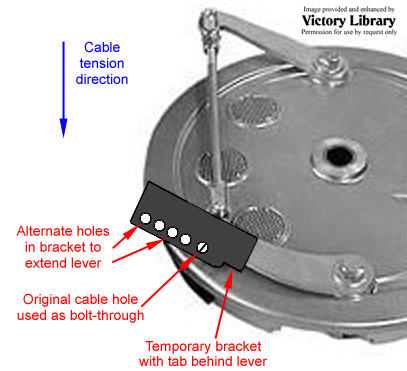
The length can be also increased by adding adapting a longer arm, or adding material to the existing arm. A small bracket can be fabricated from flat steel or aluminum stock at least the same strength as the existing cam lever, and attached to the original cable clevis, heim or rose joint hole in the cam lever with a high-quality bolt and Nyloc nut. |
If the clevis is 6mm, the clevis hole should be enlarged with a drill to 8mm or larger so that the bolt has sufficient shear strength for safety. A portion of the bracket extends inward and behind the cam lever, and is held in tension by the cable. A new cable clevis hole of the original size is at the opposite end, at increased distance from the cam. The extended Norton arms shown, above right, are available from muttznuts. Click the picture for a larger view. |
The new mechanical advantage is the ratio of (new lever) ÷ (old lever). The minimum safe separation distance for a new clevis hole is roughly the hole diameter. A new 8mm hole should be centered 12mm away from the old edge (16mm on centers), leaving 8mm of metal between the holes. Additional holes may provide alternate choices. A test under severe conditions will determine which hole provides | |
|
best control and effect, without bottoming the hand-lever out on the bars. Once this position is known the remainder of the bracket can be removed to save a few grams. The final construction can permanently attach the bracket by welding, rivetting, an extra bolt, &c. and painted, chromed &c. for corrosion resistance. Shown, right, is a fabricated bracket used on a Grimeca 2LS panel. The bracket angle is exaggerated for illustration, the actual angle should be less radical to reduce the amount of additional cable slack needed. Click the picture for a larger view.
The desired cam lever position on the backing plate may require re-shaping the lever’s point of attachment to the cam, by welding the hole closed and re-drilling or cutting the lever and re-angling it. In some cases a similar lever from another brand or model will provide an alternate “clock” position.
A “snail cam” (similar to the late Ford Mustang clutch cable mechanism) could be incorporated into the motion path, which will change the leverage from low effort/high travel for the initial cable pull to take up all slack, then gradually change to high effort/low travel to apply maximum force to the brake cam just before shoe contact is made with the drum. The leverage ratio can be anything you wish within the confines of available space, from 1.1:1 to 3:1.This is not a plug-in but an engineering project, and will require considerable development time and fabrication skills. |
Backing plate compliance |
In some cases, the backing plate is not rigid enough to prevent bending on full application. This angles the shoes away from complete contact with the drum ID. A brace can be fabricated to lock the anchor posts of DLS or 4LS shoes together diagonally. Since this is in compression when loaded (to prevent the cams from being squeezed together, reducing motion to the shoes) it must be substantial in cross-section and mount without end-play. |
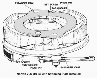
The Norton factory offered this kit (available as 06-3410 from British Cycle Supply, click here to see their page:  ) to improve the rigidity of the Commando dual leading shoe front drum brake based on a circular stiffening plate (”brake support plate”) and hardware to attach it to the existing backing plate, including replacement cams and posts with female thread to attach the support plate bolts. ) to improve the rigidity of the Commando dual leading shoe front drum brake based on a circular stiffening plate (”brake support plate”) and hardware to attach it to the existing backing plate, including replacement cams and posts with female thread to attach the support plate bolts. |
|
|
The plate’s circular shape, although necessary to provide room for the axle in the center, reduces the rigidity considerably and requires the plate to be substantially more robust to be effective. Click the picture for a larger view. |
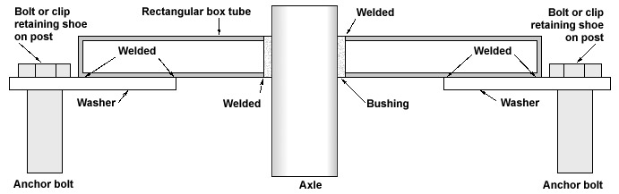
A possible anchor location for a stiffening device is the thick washer frequently used to hold the fixed shoe end to its post. New washers as thick as possible (to just clear the existing fasteners) can be welded to the ends of a rectangular box-section tube, or simply extend the |
|
|
bottom of the box enough to drill the holes. A hollow box, although much more difficult to fabricate, saves most of the weight compared to a solid flat plate, but has almost as much stiffness. The box width should be sized to a tight fit when the backing plate is relaxed, and as thick as possible to just provide clearance to the backing plate when assembled.
As shown in the Norton photo, the center must be open for axle clearance. Cut a piece of tubing with the ID 1/8” larger than the axle and the length matching the box thickness. Drill a hole matching the tube’s OD through the box, insert the tube and weld or braze in place on both sides. Ideally, the axle should be a much closer fit, even to the point of passing through a small bushing fixed in the plate. The smaller hole increases stiffness somewhat, and the axle itself will then also prevent movement. Click the picture (sorry, not to scale) for a larger view. |
Cooling |
If the brake works well, the drum will quickly absorb heat. This causes several problems:
The drum will not remain dimensionally accurate when hot, but distort and present a tapered (“bell-mouthed”) shape to the shoes at the open end to some degree greatly dependent on the drum OD’s thickness and rigidity as a cylinder. The shoes will only make partial contact and wear unevenly. Stretching under heat and pressure is a factor with all drums, and an advantage to double-sided drums because each lining surface is ½ the width of comparable single-sided drum, so it’s more resistant to distortion.
A substantial steel band or ring (3/8” thick by 1/2” tall?) could be used as a clamp, heated for expansion then fitted to the exterior of the drum. It must be a close fit (which means turning the drum OD to create a smooth surface), but also a fit that does not loosen with temperature, so an aluminum ring must be much hotter for proper shrinkage. Remember that this is unsprung rotating weight, and negatively affects suspension, acceleration, and braking - don’t use it unless you have to. The drum should be skimmed to insure concentricity after installation. However, a band won’t do much for heat because there are now 2 thermal gradients (drum to band, band to disc) where there should be none, and the transfer X-sectional area is very thin so heat transfer is very slow. It’s not an accident that the best drums are cast alloy with a steel liner so that heat flow to the drum OD is excellent.
The drum’s ability to absorb more heat goes down as its temperature goes up, which reduces braking effectiveness. This is called “heat fade”.
If this heat is not controlled, the high temperature will reach the hub, the grease in the wheel bearings will liquify and the bearings will fail.
Do not chrome, polish, coat or paint any brake parts except as needed to prevent corrosion. All surface coatings are a barrier to heat loss by radiation and convection. Although some increase the surface area by darkening the color, unless sparingly applied the result may still be a net loss. The best surface preparation for aluminum is sand-blasted, then black anodized. |
Various devices have been used to increase the surface area of a brake for added convection cooling, such as “bacon slicers”, “pie plates”, fins &c. as shown, right, but these add to unsprung weight and gyroscopic inertia, and absorb very little heat from the brake due to very thin cross-sectional area at the point of transfer. For best effect, these devices should be flat black, and soldered or brazed in place. If they’re shiney and bolt-on they’re just eye candy. | |
|
An aluminum disc could be tig’d to the OD of an aluminum drum, but for best effect the path of heat conduction from the shoe-liner-OD-disc would require almost a continuous bead and excellent mechanical fit before welding. The only advantage to simply welding continuously is that you don’t have to find a 15” lathe to machine the fins afterward.
If accurate expansion data could be found, an alloy disc could be heated, then quickly pressed onto the OD of a cast-iron drum. Shrinkage on cooling would have a compressive force, both insure stable mounting but also a good thermal interface. This must be done accurately and carefully, since too much heat will cause the disc to contract too much on cooling and either crack or over-stress the drum. Not enough heat will cause a loose fit on cooling with reduced heat transfer.
The drum ID must be turned afterward, of course - hopefully it’s still within limits. This would not only forestall heat fade after a high-speed stop (it’s the 2nd stop that kills you - the liner can’t accept any more thermal load from the shoes since it’s already glowing) but also prevent the drum shape from going weird from heat, and also the “band” effect constricting the expansion under the disc.
Drilling holes can increase cooling slightly, although the obvious purpose is weight reduction. The “cross-over” point for hole size is where the radius of the hole becomes larger than the depth of the hole. A hole larger than twice the thickness removes more area from the surface (2 × Pi × D/2^2) than is exposed in the hole (Pi × D × D/2). For a 6mm thick flange &c. the maximum hole size is 12mm:
New surface area exposed: 3.1416 × 12mm × 6mm = + 226mm2.
Existing surface area lost: 2 × 3.1416 × 6mm^2 = 226mm2. If the hole diameter is enlarged to 14mm (in the same 6mm flange), the new material exposed is 3.1416 × 14mm × 6mm = + 264mm2, but the area of material lost is 2 × 3.1416 × 7mm^2 = 308mm2. Since the surface area inside the hole is shielded from the convection airstream, even a hole smaller than indicated will give a net loss in cooling unless the hole perforates the flange and permits air circulation. A blind hole is almost useless for heat loss.
The OD of a drum between the spoke flanges can be inletted on a large lathe to form parallel ribs, which increases the cooling surface area. However, it does not remove as much weight as simply turning the excess aluminum off completely.
The next step is getting rid of the hot air. You’ll see backing plates with scoops and vents, but I prefer a scoop on the backing plate for air entry and exit holes in the drum, which promotes ventilation across the shoes.
Air entry
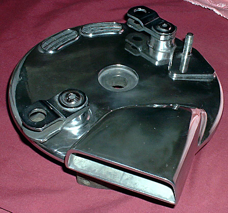
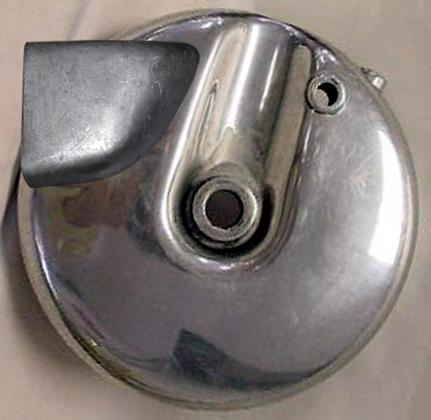
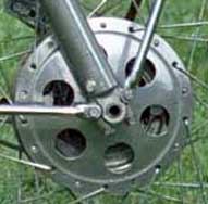
The 1971-72 BSA & Triumph conical backing plate (below, left) shows the scoop entry standing away from the plate. Next to it is the same scoop grafted on to a Harley-Davidson 1949-68 drum brake. Click the pictures for a larger view. The air entry is already provided in many other 2LS brakes as a cast-in scoop in various shapes, and need only be opened to the maximum practical size without inviting breakage, and a finer screen or grate substituted for the restrictive original. In some cases, there either is no existing scoop or it’s too small or badly placed. |
Air approaching the motorcycle spills off the tire and wheel, and away from the inlet at the speed you need the brake most. The scoop entry must stand proud of the backing plate surface or much of the area will not be exposed to the airstream at any useful speed. The scoop must be more outboard to catch “clean” air passing outside the | |
|
wheel’s shadow. I imagine it still has some effect due to the stiffening ribs in the “blind” side of the drum acting a a propeller and drafting some air through - just not as effective, but better than closed off. The exact distance is not clear and will depend on the clocking of the scoop, width of the fork legs, diameter of the front tire, fender width &c., all of which re-direct air around and into the brake. Don’t assume that the wheel itself obstructs airflow, in some cases the front of the engine carries a “plug” of still air ahead of it at cruising speed, and the wheel actually improves flow to the brake. |
A new scoop may be made from any material than can be securely attached, and where either the material or its shape make it rigid enough to retain its shape at speed. Thin gauge aluminum sheet can be easily bent over a large pipe into a conical shape, cut with a saw, and attached to the backing plate with pop rivets or small screws. Here’s a Honda 350 180mm backing plate with a fabricated scoop heli-arced in place. | |
|
Note the holes drilled for air transfer inside the scoop. Click the picture for a larger view. |
The scoop area used by serious (meaning “expensive”) Ceriani, Grimeca, &c. brakes is very large. Since the scoop is not easy to place in undisturbed air, the size should be generous, especially where the brake is small for the chassis weight, speeds are high, the course has many curves requiring braking with no prolonged period of acceleration to permit brake cooling, &c.
The shape of the scoop’s opening edge should be a generous radius (3/8” minimum, 1/2” preferred) to give the highest airflow for the smallest area.
Fabrication of a trumpet extension looks attractive but remember that this adds weight, and the horn itself is cantilevered from the point of attachment on the backing plate. If it fractures during the race, the horn may go under the tire, become wedged between the wheel and fork, &c. but in any case its cooling effect is gone and the brake will begin to overheat immediately. If you decide to make the horn large for area and clearance to the backing plate components (as in the conical brake shown) the attachment area must be large and sturdy.
There should be a generous radius on the ID of the scoop where it joins the backing plate. The area of the backing plate opening need not be as large as the scoop area, since the air will slow down immediately when it expands into the larger area in the brake’s interior and be converted to pressure. This pressure is higher than the atmospheric, so the air will be forced out of the drum vents without any air management devices on the drum.
The possible, the air inlet scoop is part of the backing plate. However, it need not be; where space is limited the front brake scoop on telescopic forks can be secured to the lower fork leg. The rear scoop can be secured to the swing-arm, rear chainguard etc. but remember it must move with rear chain adjustment. If a good seal between the scoop edge and the backing plate hole isn’t possible, use a section of foam or rubber gasket.
|
Air exit |
The air exit area must be at least as large as the entrance since the exhaust air is hot; I suggest 25% larger area as a minimum, which may be shared between several holes. The drum is a good choice for an exit since metal removed also lightens rotational inertia. For a vented drum, the hole pattern normally avoids the stiffening ribs cast into the inner wall of the drum’s back face. The holes can be as large as 1¼” |
|
|
OD if they fit comfortably between the ribs and don’t reduce its rigidity too much. A hole should never end adjacent to a change in cross-section, &c. and always leave undisturbed metal between the hole and any other surface, but force exiting air to pass as close to the shoes and the drum’s hot inner friction surface as practical. Using a larger number of smaller diameter holes allows closer placement to the drum OD. The pattern should be radially symmetrical in any case for aesthetic effect and to minimize re-balancing. Here’s a Honda 350 180mm drum, click the picture for a larger view.
In some cases the backing plate is the only available location for an exit. Here the exit hole(s) must be far away from the entry making the path as long as possible to force air to absorb heat from the shoes and drum. A ¼-circle of small diameter holes 180° away from the entry and close to the OD is the general idea, similar to that shown above, and here: .
A 4LS brake cannot be vented to the atmosphere through the drum, since the two drums are back-to-back. However, if the intake air pressure to the backing plates is high enough even small radial holes in the drum OD next to the lining will do something; otherwise the exits must be in the rear of the backing plates. |
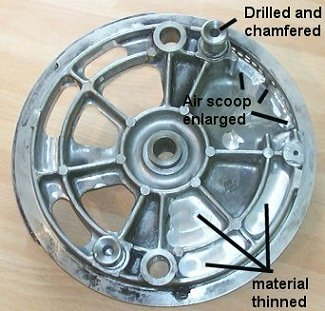
Weight reduction |
Weight removal is fairly straight-forward on all original equipment brakes, since manufacturers are more concerned with labor and machining costs than reducing unsprung weight by that last 5 grams. Obviously, areas under high stress such as axle support, torque anchor stud and cam lever bosses, and webbing supporting the drum’s friction surface must be kept strong enough to prevent breakage, but also | |
|
sufficiently stiff and rigid to prevent flexing. Here is a Suzuki GT750 backing plate after radical machining for weight removal, click the picture for a larger view.
The most effective weight removal is at the maximum distance from the center of rotation, since this has the highest gyroscopic inertia: the drum OD, spoke flanges &c. The flanges can be thinned from both sides on a large lathe, but be careful not to reduce the thickness at the spoke holes too much. Holes large enough to leave only ¼” of metal remaining between the hole and the outer rim and the hole and the drum OD can be evenly spaced between spoke holes. E.g. if the flange height is 1” tall, a ½” hole is safe, &c. The drum’s OD can be reduced slightly, but this is only suitable where the iron liner is fairly thick and will remain geometrically correct even when loaded and hot.
The drum can be both lightened and ventilated by drilling or milling holes through its vertical panel surface (directly opposite the backing plate). If there are stiffening ribs connecting the bearing hub to the panel the holes should be centered between rib pairs, and not actually remove any metal from the small radius where the rib joins the parent casting. Shenton suggests that the pattern for the BSA/Triumph 1968-70 8” 2LS drum should be five 1¼” holes equally-spaced along the mid-line. Weight removal from the drum should be radially symmetrical since it affects balance, and the wheel must be re-balanced after all weight removal operations are completed. Please see comments above regarding hole placement for optimum air circulation, which should be given priority over weight reduction. |
If the drum or hub is stiffened by cast-in ribs or vanes, the pattern and number of holes should be divisible by the number of ribs. E.g., the 1971-73 Triumph & BSA conical drum has 5 ribs, use a radially symmetrical pattern of 5, 10, 15 &c. holes. This conical rear hub, modified and contributed by BritBike Forum member “featherbred”, has | |
|
holes alternating with the ribs to reduce weight without compromising stiffness. |
Although the backing plate, shoes and torque arm do not rotate, they’re still unsprung weight and greatly affect handling and especially how well the suspension reacts to bumps and ripples. Weight can be removed by drilling through the web supporting the lining area of the shoes. The shoe itself may be wider than needed to support the lining and may be scalloped away to only 1/8” wider than the lining to |
|
|
prevent cracking except in areas where the shoe width positions the shoe laterally between the drum and backing plate. If new lining is to be applied (rivetted or bonded) a carefully spaced pattern of small (1/8”) holes may be drilled in the metal of the shoe, although this is only suitable if the shoe has generous webbing to resist deformation when applied. The torque arm can be lightened considerably since it’s always in tension and therefore need not resist bending. In fact, a 5/32” wire cable is sufficient for most use, althought I certainly wouldn’t go that far. Here’s a pair of shoes with a simple hole pattern, click the picture for a larger view.
Be careful to de-burr and radius all cuts. Weight removed from the backing plate and shoes doesn’t affect wheel balance. |
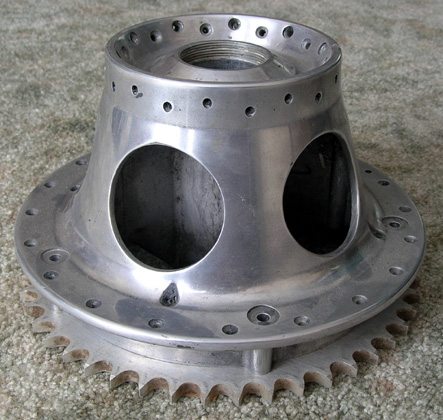
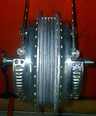
Suzuki 4LS |
The earliest Suzuki GT750 water-cooled 2-stroke 3 cylinder models used a very powerful and heavy 4 leading shoe brake.
It’s a tight fit in most drum brake forks, since it needs about 185mm
(7.28”) center to center on the fork tubes for clearance. However, the
brake backing plates can be trimmed back at the axle support boss. Click the picture for a larger view. |
|
|
The 1972 Suzuki GT550 air-cooled 2-stroke 3 cylinder model also used a 4LS front drum brake, but
the width across the backing plates was about 6mm (¼”) narrower. This makes it a better choice for smaller forks such as Betor, Ceriani and original British equipment. |
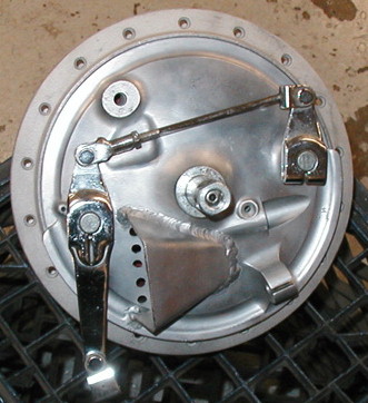
Here is a Suzuki GT750 after machining for air exit through the backing plates since there is no drum surface available. The original scoop is at 10 o’clock. Click the picture for a larger view.
I’ve prepared a Table comparing many brake drum systems by diameter, area and method of actuation. Click below to see it. |
|
|
|