|
|
 |
In this series, I will not repeat the information that is already available on how superchargers work, but instead focus on their selection, installation, use and tuning on older engines. Here I will make various observations and comments on function, and in some cases how to make improvements. New material will be added regularly, and eventually better organized. Click below to jump directly to an individual topic. |
Supercharger Topics |
|
|
|
|
|
|
Function |
|
|
|
|
|
Engine Design Changes
Constructing a serious motor for supercharger use requires different priorities than a normally-aspirated motor. Here I will touch on some of the more important factors regarding the details of the motor itself. The assumption made is that the motor is being either built or re-tuned to make optimum use of a supercharger, although in general many of the comments apply to turbocharger and nitrous-oxide use as well. The parameters for positive displacement and centrifugal superchargers are slightly different, and will be separated by type where appropriate. |
Intake
The intake port’s cross-sectional area is no longer the limiting factor in power production, as is frequently true in engines in a low state of tune or development. Porting as it refers to changes in port shape (rather than mere enlargement) still provides a benefit by reducing parasitic pumping loss during the intake stroke. Intake port size may be kept as original, unless a known and proven modification to the shape (rather than the size) can be performed.
The std. intake port & valve are normally larger than
the exhaust port & valve, as the mechanical pressure of the rising piston is more efficient at expelling exhaust gas than the vacuum of the descending piston is at drawing fresh mixture in. If the motor was originally well designed for normally aspirated use, the relative efficiency of flow between the two sides will be nearly equal, in fact differences in cam timing between intake and exhaust frequently have as their purpose to adjust any disparity. This relative flow balance between the intake and exhaust sides is affected by supercharger use: the intake is now much more efficient.
Exhaust
For best effect the entire exhaust system should be re-designed towards a larger displacement motor, requiring more flow from every component. The exhaust system (cam, tappet shape, rocker ratio, valve size, port size & pipe size) is not especially sensitive to the boost itself, but only to the increase in exhaust gas flow, regardless of the source. The “target size” of the exhaust components is roughly based on the amount of boost to be used. For example: a 300” motor developing 250 HP in normally aspirated tune may develop 350 HP on boost, and should have an exhaust system suitable to (obviously) 350 HP, more like a 400” motor. This is especially true since boost adds torque throughout the rpm range, not just peak power. The motor becomes more like a milder but bigger motor, rather than a more powerful “race” version of the same size motor.
The std. exhaust valve size should be increased by between .060” and .080” (1.5mm-2mm). The new area (not diameter) should be between 75 & 80% of the intake valve area. In many cases only a slight increase is possible using the original cast-in seat insert but this should still be done.
A large engine and high boost may use a valve as large as 1/4” (6.35mm) oversize. In a serious (high boost) motor, this may require a reduction in the choice of intake valve size as a compromise, since some clearance between the valves is needed not only to prevent clash in operation, but for added cooling of the head casting between the seats. In some cases, an older but interchangable head casting of the same type is a good choice since its intake valves may be smaller (e.g., a 283 head instead of a 350 head).
For serious high boost applications consideration should be made to using a valve as large as 90% of the intake valve area to be fitted. The size will still be limited by the point where the seats almost touch as described.
The exhaust valve head diameter sizes listed below are not requirements but improvements. An engine with insufficient exhaust valve area will not produce as much power due to pumping loss. If you cannot or will not increase the exhaust:intake flow proportion by using larger exhaust valves, most of the improvement can be obtained by changes to the cam timing but this is not as effective.
5 psi Boost: Exhaust = 75% of Intake Area |
In. | 2.00” | 1.95” | 1.90” | 1.85” | 1.80” | 1.75” | 1.70” | 1.65” | 1.60” | 1.55” | 1.50” | 1.45” | 1.40” | 1.35” | 1.30” | 1.25” | 1.20” |
Ex. | 1.73” | 1.69” | 1.65” | 1.60” | 1.56” | 1.52” | 1.47” | 1.43” | 1.39” | 1.34” | 1.30” | 1.26” | 1.21” | 1.17” | 1.13” | 1.08” | 1.04” |
10 psi Boost: Exhaust = 80% of Intake Area |
In. | 2.00” | 1.95” | 1.90” | 1.85” | 1.80” | 1.75” | 1.70” | 1.65” | 1.60” | 1.55” | 1.50” | 1.45” | 1.40” | 1.35” | 1.30” | 1.25” | 1.20” |
Ex. | 1.79” | 1.74” | 1.70” | 1.65” | 1.61” | 1.57” | 1.52” | 1.48” | 1.43” | 1.39” | 1.34” | 1.30” | 1.25” | 1.21” | 1.16” | 1.12” | 1.07” |
15 psi Boost: Exhaust = 85% of Intake Area |
In. | 2.00” | 1.95” | 1.90” | 1.85” | 1.80” | 1.75” | 1.70” | 1.65” | 1.60” | 1.55” | 1.50” | 1.45” | 1.40” | 1.35” | 1.30” | 1.25” | 1.20” |
Ex. | 1.84” | 1.80” | 1.75” | 1.71” | 1.66” | 1.61” | 1.57” | 1.52” | 1.48” | 1.43” | 1.38” | 1.34” | 1.29” | 1.24” | 1.20” | 1.15” | 1.11” |
20 psi Boost: Exhaust = 90% of Intake Area |
In. |
2.00” | 1.95” | 1.90” | 1.85” | 1.80” | 1.75” | 1.70” | 1.65” | 1.60” | 1.55” | 1.50” | 1.45” | 1.40” | 1.35” | 1.30” | 1.25” | 1.20” |
Ex. | 1.90” | 1.85” | 1.80” | 1.76” | 1.71” | 1.66” | 1.61” | 1.57” | 1.52” | 1.47” | 1.42” | 1.38” | 1.33” | 1.28” | 1.23” | 1.19” | 1.14” |
The exhaust seat should be 30° (instead of 45°), although this requires a substantial oversize. A 30° seat increases low-lift flow, and the added release of exhaust as the valve just cracks open is very helpful. A 30° seat requires a new valve with a head diameter larger than the original. The amount to be added to the existing valve diameter is not proportionate to the valve size but to the seat width. Why not use a 30° seat on the intake as well? Because intake efficiency is more effectively supplied by boost, and also that the shallow seat will increase overlap effects, which we do not want.
The exhaust valve face width and seat width should be increased somewhat to allow greater heat transfer. I suggest .080” as a minimum. Some additional stem-to-guide clearance may be needed, .001” or so.
After the seats have been cut, the exhaust bowl area should be increased to match the new seat area. In some cases, the edge of the combustion chamber nearest the valve head should be moved back a bit (towards the edge of the bore) to prevent shrouding the valve. The bore (in the cylinder) may also benefit from a notch to permit flow around the valve head - be careful not to intrude into the ring path.
The exhaust port ID should be enlarged proportionate to the new valve size, as practical. Do not attempt to match the port ID to the primary pipe ID, or even blend or taper the transition area. The change in shape between the port and pipe should be abrupt.
Exhaust Pipe
The diameter of the primary exhaust pipe should be increased, usually by 1/8” to 1/4”, even if the actual port cannot be made larger. Under no circumstances should any form of internal baffle be inserted. If you need a muffler, find a good one with capacity sized to the new power level rather than the displacement, as described above. An RPM-sensitive tuned primary length will still work but has less effect since both ports are under positive pressure. |
Cams |
Cams for boosted engines should generally be milder in duration than for normally aspirated engines designed for high peak power. Extended timing is no longer needed to produce peak power, and will interfere with boosted operation.
Adjustments to the intake:exhaust flow balance are frequently made by extending the cam timing on the side with lesser efficiency. Since boost only improves the flow of the intake system, any flow bias change that cannot or has not been made through increased exhaust efficiency (as described above) requires a cam choice with added weight to exhaust duration, generally 10° more than the intake duration. This frequently means that intake duration is reduced (from normally aspirated) by 10 or 20°, and exhaust duration is reduced by 0 to 10°. E.g., 300° intake & 300° exhaust becomes 280° intake & 290° exhaust.
The intake valve opening point should be retarded (closer to TDC) to reduce overlap. The intake valve closing point should be advanced (closer to BDC), since the static compression ratio will be lower. This preserves cranking compression, and is not as useful for peak power as boost pressure. The result is a shorter intake duration.
The exhaust valve opening and closing points are especially sensitive. The exhaust opening point determines how much of the work cycle is used as energy, the remainder being wasted as heat through the open valve. A supercharged engine develops a higher percentage of its useful work later in the cycle (compared to a high-compression normally aspirated engine), and opening the valve early is throwing away an advantage.
However, keeping the valve closed too long (i.e., closer to BDC) wastes power by requiring additional effort ABDC to expel the remaining exhaust gas.
The opening point is, therefore, a delicate balance, where as the opening point is delayed more of the power is transferred to the crankshaft, but part of it is needed to “push out” the remaining gas. Where this balance point tips depends largely on exhaust valve size. A large exhaust valve allows late opening because a higher volume of gas is released immediately without the need for a longer time interval. If the valve size is not sufficient, the valve must open earlier.
To summarize: exhaust improvements required, in order of preference:
1. larger exhaust valve
2. higher ratio exhaust rocker arm
3. earlier exhaust valve opening.
The requirements for positive displacement and centrifugal superchargers differ here.
The preferred lobe separation angle (intake to exhaust centerlines) is generally wider than used in performance applications, usually between 112-118°. |
Cam Terms and Symbols |
Term | Before top dead center | After top dead center | Before bottom dead center | After bottom dead center |
Symbol | BTDC | ATDC | BBDC | ABDC |
Term | Intake valve opens | Intake valve closes | Exhaust valve opens | Exhaust valve closes |
Symbol | IO, IVO | IC, IVC | XO, EO, EVO | XC, EC, EVC |
Term | Intake lobe centerline | Exhaust lobe centerline | Lobe separation angle |
Symbol | ICL | XCL, ECL |
LSA, LCA |
Value | Formula |
Example, using 34-70, 74-26 timing |
Intake duration | IO + IC + 180° |
34 + 70 + 180 = 284° |
Exhaust duration | XC + XO + 180° |
74 + 26 + 180 = 280° |
Overlap | IO + XC |
34 + 26 = 60° |
Intake centerline | (IC - IO) ÷ 2 + 90° ATDC | 70 - 34 = 36; 36 ÷ 2 = 18; 18 + 90 = 108° |
Exhaust centerline | (XO - XC) ÷ 2 + 90° BTDC |
74 - 26 = 48; 48 ÷ 2 = 24; 24 + 90 = 114° |
Lobe separation angle | (ICL + XCL) ÷ 2 | 108 + 114 = 222; 222 ÷ 2 = 111° |
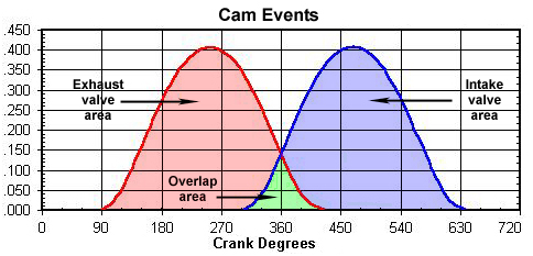
Please note that overlap may be evenly disposed around TDC (e.g., IO = XC), but this is not always true. The LSA is frequently different from where the cam is “timed in”. There is no magic figure for any of these values, only tendencies. The LSA is used as a control to prevent overlap from becoming too large when the duration of the intake, exhaust or both lobes are ex- | |
|
tended. Under ideal conditions, boost pressure will “flush” exhaust gas from the chamber during the overlap period, but this is sensitive to RPM and careful tuning and is not present at all speeds. Click the picture for a larger view. Engines with mild cams may work best with the original LSA.
The exhaust event should also be sped up. This is difficult in most engines, but where possible a higher ratio rocker arm should be used on the exhaust valves only.
Valve springs
The valve spring tension, both when the valves are seated and open, is normally a function of maximum engine speed, valve train component weight, and the rate at which the cam opens and closes the valves. To this must be added some compensation for the fact that, under boost, intake charge pressure will oppose the intake valve’s closing. Vizard suggests that a useful figure is 75% of the intake valve area (OD × .7854) multiplied by the maximum boost pressure. E.g., a 1.50” intake valve has an area of 1.767”. With 10 psi boost, the figure becomes 17.7 lbs.; 75% of this is roughly 13 lbs. Add this amount to the seated pressure.
|
Ignition
Maximum spark advance must be reduced, at least during periods of boost. This is especially important in high gear, as the motor is under maximum load (no torque multiplication, and wind resistance as well as vehicle weight must be overcome). High power-to-weight ratio engines may tolerate near-normal spark advance in low gear only.
If no spark retard device is used, the ignition advance should be re-curved for best effect. The requirement for positive displacement and centrifugal superchargers are slightly different.
A motor with a positive displacement supercharger will need slightly less initial advance with the remainder added to the mechanical advance mechanism, and a slower curve to delay additional spark until higher speed, perhaps 500-1000 RPM.
A motor with a centrifugal supercharger will accept the same or even slightly more initial advance, with the reduction taken from the mechanical advance.
Ignitions with vacuum advance provisions should increase the vacuum rate to match the original total spark setting with vacuum.
Colder spark plugs must be used, with reduced gap to compensate for the higher cylinder pressure. A short ground electrode is extremely important. This allows for a shorter heat path, so the ground electrode does not become incandescent and serve as an extra ignition source.
The extreme increase in cylinder pressure will require more spark intensity - a high-output system is strongly suggested (magneto or MSD, Crane, &c. electronic), complete with good coil and wires.
Temperature
Combustion temperature is also affected by mixture
strength. “Stoichiometric” (chemically correct) mixture is not safe for boost applications (and not effective for maximum power in NA applications). Slightly rich, between 12.0-12.5:1 air:fuel by weight is a good start. The extra fuel improves power by cooling the chamber, and preventing detonation. Richer mixture also burns more slowly than correct mixture, delaying the point of maximum cylinder pressure. Careful experimentation by reducing the jet size very slightly from full rich may improve power, but plug color is not a reliable method of monitoring this. Because of the increased peak power, a slight increase in air correction size and a disproportionately large increase in main jet size is frequently called for.
Fuel
The stock fuel line is not adequate. The line size should be up-graded to 1/2”, and all fittings, filters, T-junctions and restrictions reviewed and re-sized as necessary.
High octane should be used for safety, and to allow spark settings for maximum efficiency during normal (non-boost) operation.
A method of controlling detonation is to introduce a material into the combustion chamber which reduces its temperature. This is best done with a liquid, and let’s use one that’s cheap, safe, easy to use, and effective: water. The commercially-available Edelbrock and Spearco water injection kits are well suited to supercharger use. Where they would normally operate during periods of low vacuum (open-throttle) with high-compression motors, they can also be triggered by the same vacuum signal just before boost goes positive.
This will not be sufficient to completely eliminate detonation with high boost, but it will allow a more normal spark advance setting and spark plug heat range. Methanol up to 50% can be added for even better effect, but watch the lines and fittings closely - methanol is very corrosive.
Compression ratio
This should be kept to a conservative level
for best effect. Streetable ratios of 8.0 to 9.0:1 reduce torque compared to 10:1, and will
make part-throttle response “soft” if a big cam with a late intake closing point is used, but permit higher boost levels.
In my opinion, there is a point of diminishing returns, where reducing the compression ratio even more (7:1, etc.) and adding more boost is not as practical, due to the reduced power in NA mode, limited cam timing, poor mileage etc. If peak power is the sole concern as in LSR competition, reducing the compression ratio to as low as 6:1 will allow considerably more boost before the onset of detonation with a gain in power, but this will make the motor more sensitive to cam timing and reduce torque in the lower RPM range, and make jetting more critical.
If the total amount of boost is known and limited by compressor size or RPM more compression can be used, but the point of detonation must be approached cautiously.
Intake charge temperature is a major contributor to spark advance sensitivity and knock resistance. According to Troy Patterson of TMP Carbs, “cold air induction buys you compression tolerance to the tune of for every 10° reduction in induction temperature, you gain approx. .01 a point in compression tolerance. 100° reduction in inlet temperature nets you a full point of compression.”. This can be done on a blow-through installation with an intercooler. In any event the air intake to the system must be positioned away from any source of heated air such as the head, cylinder or exhaust.
The effective compression ratio is not an exact figure since there are many variables that are difficult to measure and quantify. The mechanical or static compression ratio does not change - it is still simply a comparison of the volume of the cylinder at TDC ÷ the volume of the cylinder at BDC. The dynamic compression ratio (incorporating the intake valve closing point) is not useful here.
The effective compression ratio may be approximated by adding the boost pressure to the atmospheric pressure, dividing their sum by the atmospheric pressure, then taking the .74074 exponent (1 ÷ 1.35, the reciprocal of the approximate ratio of variable heats) of the result, and multiplying this by the original compression ratio. This ratio of variable heats does not mean that some engines and conditions will not need other factors plugged in to get the numbers (effective knock resistance) closer to real world. The “real” ratio is 1.4, and almost all data-based math uses a slightly smaller number, down to about 1.19, since it varies not only with the combustion process but also with the water temperature and how much heat is lost through the walls, etc. (ceramic cylinder walls permitting minimal thermal loss would be closer to 1.39, silver walls permitting massive thermal loss would be closer to 1.1).
This complex relationship was developed by TFX Engine Technology Inc., and graciously furnished by Clint Gray.
To approximate the effective compression ratio from the static compression ratio and boost, where:
ECR: effective compression ratio.
CR: static (nominal) compression ratio; e.g. 7.5:1.
B: boost, in pounds per square inch (psi).
A: atmospheric pressure, in pounds per square inch (psi); 14.696 is approximately correct for sea
level and 70° F.
|
ECR = CR × ((B + A) ÷ A).74074 |
Example 1, an engine with 8.0:1 static compression ratio and 10 psi of boost at sea level:
CR = 8.0
B = 10
A = 14.696 |
ECR = 8 × ((14.696 + 10) ÷ 14.696).74074, or 8 × (24.696 ÷ 14.696).5, or 8 × (1.6805).74074, or 8 × 1.469, or 11.75.
The effective compression ratio is 11.75:1.
|
Example 2, an engine with 9.0:1 static compression ratio and 15 psi of boost at 1000 foot (higher) elevation:
CR = 9.0
B = 15
A = 14.16 (approximately) |
ECR = 9 × ((14.16 + 15) ÷ 14.16).74074, or 9 × (29.16 ÷ 14.16).74074, or 9 × (2.0593).74074, or 9 × 1.708, or 15.37.
The effective compression ratio is 15.37:1.
The table below shows common values of boost in psi, and their effect on compression ratio based on atmospheric pressure of 14.696 psi or 29.92 Hg” (sea level). Higher elevation will change the values, of course.
To use this table, find your static (nominal) compression ratio in the left column, then follow across to your anticipated boost pressure. This cell contains your effective compression ratio, for purposes of comparison only. Any value above 9.0:1 will generally require high octane gasoline, values above 12.0:1 will require racing gasoline, an above 14.0:1 will require methanol. This is similar to the requirements for normally aspiration engines but with the added input of higher charge temperature and lower heat rejection at higher power levels. |
Effect compression ratio under boost @ atmospheric pressure = 14.696 psi |
Boost | 5 psi | 6 psi | 7 psi | 8 psi | 9 psi | 10 psi | 11 psi | 12 psi | 13 psi
14 psi | 15 psi | 16 psi | 17 psi | |
Multiply CR by | 124% | 129% | 133% | 138% | 142% | 147% | 151% | 156% | 160% | 164% | 168% | 173% | 177% |
CR: 5.0:1 | 6.2:1 | 6.5:1 | 6.7:1 | 6.9:1 | 7.1:1 | 7.4:1 | 7.6:1 | 7.8:1 | 8.0:1 | 8.2:1 | 8.4:1 | 8.7:1 | 8.9:1 |
CR: 5.5:1 | 6.8:1 | 7.1:1 | 7.3:1 | 7.6:1 | 7.8:1 | 8.1:1 | 8.3:1 | 8.6:1 | 8.8:1 | 9.0:1 | 9.2:1 | 9.5:1 | 9.7:1 |
CR: 6.0:1 | 7.4:1 | 7.7:1 | 8.0:1 | 8.3:1 | 8.5:1 | 8.8:1 | 9.1:1 | 9.4:1 | 9.6:1 | 9.8:1 | 9.1:1 | 9.4:1 | 9.6:1 |
CR: 6.5:1 | 8.1:1 | 8.4:1 | 8.6:1 | 9.0:1 | 9.2:1 | 9.6:1 | 9.8:1 | 10.1:1 | 10.4:1 | 10.7:1 | 10.9:1 | 11.2:1 | 11.5:1 |
CR: 7.0:1 | 8.7:1 | 9.0:1 | 9.3:1 | 9.7:1 | 9.9:1 | 10.3:1 | 10.6:1 | 10.9:1 | 11.2:1 | 11.5:1 | 11.8:1 | 12.1:1 | 12.4:1 |
CR: 7.5:1 | 9.3:1 | 9.7:1 | 10.0:1 | 10.4:1 | 10.7:1 | 11.0:1 | 11.3:1 | 11.7:1 | 12.0:1 | 12.3:1 | 12.6:1 | 13.0:1 | 13.3:1 |
CR: 8.0:1 | 9.9:1 | 10.3:1 | 10.6:1 | 11.0:1 | 11.4:1 | 11.8:1 | 12.1:1 | 12.5:1 | 12.8:1 | 13.1:1 | 13.4:1 | 13.8:1 | 14.2:1 |
CR: 8.5:1 | 10.5:1 | 11.0:1 | 11.3:1 | 11.7:1 | 12.1:1 | 12.5:1 | 12.8:1 | 13.3:1 | 13.6:1 | 13.9:1 | 14.3:1 | 14.7:1 | 15.0:1 |
CR: 9.0:1 | 11.2:1 | 11.6:1 | 12.0:1 | 12.4:1 | 12.8:1 | 13.2:1 | 13.6:1 | 14.0:1 | 14.4:1 | 14.8:1 | 15.1:1 | 15.6:1 | 15.9:1 |
CR: 9.5:1 | 11.8:1 | 12.3:1 | 12.6:1 | 13.1:1 | 13.5:1 | 14.0:1 | 14.3:1 | 14.8:1 | 15.2:1 | 15.6:1 | 16.0:1 | 16.4:1 | 16.8:1 |
CR: 10.0:1 | 12.4:1 | 12.9:1 | 13.3:1 | 13.8:1 | 14.2:1 | 14.7:1 | 15.1:1 | 15.6:1 | 16.0:1 | 16.4:1 | 16.8:1 | 17.3:1 | 17.7:1 |
Boost | 18 psi | 19 psi | 20 psi | 21 psi | 22 psi | 23 psi | 24 psi | 25 psi | 26 psi | 27 psi | 28 psi | 29 psi | 30 psi |
Multiply CR by | 181% | 185% | 189% | 193% | 197% | 201% | 205% | 209% | 213% | 217% | 220% | 224% | 228% |
CR: 5.0:1 | 9.1:1 | 9.3:1 | 9.5:1 | 9.7:1 | 9.9:1 | 10.1:1 | 10.3:1 | 10.5:1 | 10.7:1 | 10.9:1 | 11.0:1 | 11.2:1 | 11.4:1 |
CR: 5.5:1 | 10.0:1 | 10.2:1 | 10.4:1 | 10.6:1 | 10.8:1 | 11.1:1 | 11.3:1 | 11.5:1 | 11.7:1 | 11.9:1 | 12.1:1 | 12.3:1 | 12.5:1 |
CR: 6.0:1 | 10.9:1 | 11.1:1 | 11.3:1 | 11.6:1 | 11.8:1 | 12.1:1 | 12.3:1 | 12.5:1 | 12.8:1 | 13.0:1 | 13.2:1 | 13.4:1 | 13.7:1 |
CR: 6.5:1 | 11.8:1 | 12.0:1 | 12.3:1 | 12.5:1 | 12.8:1 | 13.1:1 | 13.3:1 | 13.6:1 | 13.8:1 | 14.1:1 | 14.3:1 | 14.6:1 | 14.8:1 |
CR: 7.0:1 | 12.7:1 | 13.0:1 | 13.2:1 | 13.5:1 | 13.8:1 | 14.1:1 | 14.4:1 | 14.6:1 | 14.9:1 | 15.2:1 | 15.4:1 | 15.7:1 | 16.0:1 |
CR: 7.5:1 | 13.6:1 | 13.9:1 | 14.2:1 | 14.5:1 | 14.8:1 | 15.1:1 | 15.4:1 | 15.7:1 | 16.0:1 | 16.3:1 | 16.5:1 | 16.8:1 | 17.1:1 |
CR: 8.0:1 | 14.5:1 | 14.8:1 | 15.1:1 | 15.4:1 | 15.8:1 | 16.1:1 | 16.4:1 | 16.7:1 | 17.0:1 | 17.4:1 | 17.6:1 | 17.9:1 | 18.2:1 |
CR: 8.5:1 | 15.4:1 | 15.7:1 | 16.1:1 | 16.4:1 | 16.7:1 | 17.1:1 | 17.4:1 | 17.8:1 | 18.1:1 | 18.4:1 | 18.7:1 | 19.0:1 | 19.4:1 |
CR: 9.0:1 | 16.3:1 | 16.7:1 | 17.0:1 | 17.4:1 | 17.7:1 | 18.1:1 | 18.5:1 | 18.8:1 | 19.2:1 | 19.5:1 | 19.8:1 | 20.2:1 | 20.5:1 |
CR: 9.5:1 | 17.2:1 | 17.6:1 | 18.0:1 | 18.3:1 | 18.7:1 | 19.1:1 | 19.5:1 | 19.9:1 | 20.2:1 | 20.6:1 | 20.9:1 | 21.3:1 | 21.7:1 |
CR: 10.0:1 | 18.1:1 | 18.5:1 | 18.9:1 | 19.3:1 | 19.7:1 | 20.1:1 | 20.5:1 | 20.9:1 | 21.3:1 | 21.7:1 | 22.0:1 | 22.4:1 | 22.8:1 |
In the table below, find your elevation above sea level and use the atmospheric pressure shown (instead of 14.696) for boost calculations. The Bonneville salt flat are shown at 4,214 feet. El Mirage Dry Lake is shown at 2,833 feet. Interpolate between the values shown for intermediate elevations. |
Atmospheric pressure vs. elevation |
Altitude above sea level Feet Meters | Barometric
pressure in Hg” | Atmospheric
pressure in Psi | % of sea level
(14.696 psi) |
Sea level | 0 | 29.92 | 14.696 | 100% |
500 | 153 | 29.38 | 14.43 | 98.19% |
1,000 | 305 | 28.86 | 14.16 | 96.35% |
1,500 |
458 | 28.33 | 13.91 | 94.65% |
2,000 | 610 | 27.82 | 13.66 | 92.95% |
2,500 |
763 | 27.32 | 13.41 | 91.25% |
2,833 (El Mirage) |
863 | 26.98 | 13.25 | 90.16% |
3,000 | 915 | 26.82 | 13.17 | 89.62% |
3,500 | 1,068 | 26.33 | 12.93 | 87.98% |
4,000 | 1,220 | 25.84 | 12.69 | 86.35% |
4,214 (Bonneville) | 1,284 | 25.64 | 12.59 | 85.67% |
4,500 | 1,373 | 25.37 | 12.46 | 84.78% |
5,000 | 1,526 | 24.90 | 12.23 | 83.22% |
6,000 | 1,831 | 23.99 | 11.78 | 80.16% |
7,000 | 2,136 | 23.10 | 11.34 | 77.16% |
8,000 | 2,441 | 22.23 | 10.91 | 74.24% |
9,000 | 2,746 | 21.39 | 10.50 | 71.45% |
10,000 | 3,050 | 20.58 | 10.10 | 68.73% |
Pistons
Cast (OEM or aftermarket) pistons will tolerate modest boost, but will fail if spark advance, jetting etc. are not accurate. The next step is hyper-eutectic (high silicone) cast pistons, such as K-B, etc. These have higher dome strength, and tolerate higher dome temperature, but are not as strong as forged pistons. Be careful to follow the manufacturer’s ring end gap specs carefully!
If using a custom forged piston (JE, Ross, Wiseco,
etc.) be sure to specify supercharger use to insure adequate dome thickness; usually .200” minimum. Thick-wall wrist pins are generally used, as a weight-saving thin-wall
pin may bend under boost.
The top compression ring end gap mustbe wider (looser) than
std. to allow for higher dome and land temperatures under boost. Rather than the usual .004” gap per inch of bore size, .006” is preferred for street use. The second ring gap goes from .0025” per inch of bore up to .0045”.
Crankshaft & Connecting Rods
Rod failure is usually in tension (RPM), and only slightly affected by boost. However, the crankshaft is under more load and must be the most modern and robust type available.
The ratio between connecting rod length and stroke length (normally represented by the symbol “n”) affects the combustion process in all engines, but has a slightly different feature in supercharger applications. The rod ratio can be calculated as follows: Ratio “n” = Rod Length ÷ Stroke.
Combustion is affected by low “n” values (short-rod, 1.5:1 to 1.7:1 or so). The increase in piston speed away from TDC on the power
stroke causes the chamber volume to increase more rapidly than in a long-rod
motor - this delays the point of maximum cylinder pressurefor best effect
under boost. Where the maximum pressure point occurs later in the cycle, the average cylinder pressure is greater without the “spike” that causes damage. Delaying the point of maximum cylinder pressure allows more boost to be used with relative safety.
Piston motion away from BDC is slower, trapping a higher percentage
of cylinder volume, making the motor less sensitive to late intake valve closing (hot cams). Intake valve closing can be slightly more radical than in a long-rod motor. For more details see my Tech Paper: “Connecting Rod vs. Stroke”, click here:  . .
See these Victory Library booklets |

|

|

|

|

|

|

|

|

|

|

|
|