|
 |
Harley-Davidson 45 Transmission Torque Plate Ideas
Purpose
The 1941-52 45 solo frame, although the
strongest of the series, have an unfortunate tendency to develop a crack on the right side, at the junction
of the seat post tube and the transmission cradle casting. This is frequently precipitated by racing, where
the power and “G” forces apply leverage from the rear wheel to this area.
The transmission design is partly to blame, since the primary chain inputs power from the engine on the left side which naturally torques the transmission forward under chain tension. The transmission sprocket on the right side transfers power to the rear wheel sprocket, and causes the inverse problem: torquing the transmission backward on the right side. Both forces combine to twist the transmission clockwise, with the torque transferring to the frame through the three 7/16” mounting studs. This tries to bend the frame at the critical area to the left.
The methods by which the frame can be made stiffer are very limited since most of the critical area is two-dimensional. Re-inforcing the frame by installing vertical struts between the upper and lower rear tubes on each side (as was done on the WR) only resist flexing and the natural counter-clockwise rotation of the transmission against torque in a vertical plane.
A potential improvement lies in a more rigid lock-up of the engine and transmission, so that the transmission’s rotation and twist are not transmitted solely into the frame. The stress vector is pitch (rotating about the crankshaft axis) in the vertical plane. The competence we're concerned with is not strength (resistance to breakage) but stiffness (resistance to bending, Young's modulus).
Steel is about 3 × as stiff as aluminum, so 1/4" should be enough. Plain mild steel plate will work fine, 4130 etc. isn't needed.
Depending on how complex the shape is, welding may not be needed - the layers can be screwed or riveted together since the fasteners are in shear.
Luckily, there are vertical parallel finished machined surfaces on the left sides of both the transmission case and left crankcase half (although they’re not on the same plane). A rigid plate connecting these two surfaces will do much to keep both chains aligned, and transfer some of the engine torque (now being absorbed by the transmission
studs) back to the motor mounts, and away from the area of known problems.
For greatest effect, the new plate must be attached at several widely-separated points to give each fastener leverage.
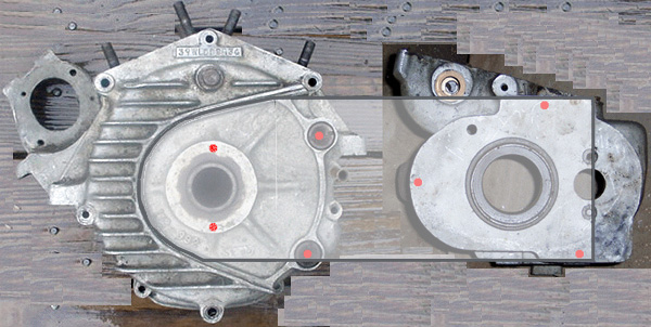
The crankcase left main bearing support boss is only 3.03" wide, so the thread size that will not intrude into the cast-in race appears to be 5/16". A 3/8” 6061 plate could be fastened to the left case (in place of the std. inner primary cover) using the two original inner primary bolts (using small cylinderical spacers to make up the extra depth) + two (or more) extra 5/16-18 NC studs drilled & tapped into the boss (shown in red). If there’s not enough room behind the chain row, 1/4” steel plate will work as well with a slight weight penalty. Needless to say, numerous holes can be drilled, and a short piece of angle can be welded length-wise to add stiffness. On the plus side, this will also be rigid enough to mount a primary shoe tensioner, so the transmission can really be tied down.
The plate extends across the left surface of the transmission case (properly spaced with an added plate for distance), and is attached by three (or more) 3/8-16 NC studs drilled & tapped as shown. The holes in the plate can be precisely slotted for primary chain adjustment. The plate both resists “cocking” (misalignment of the engine sprocket shaft and transmission mainshaft due to torque) and rotation due to power, and relieves the torque through the transmission mount.
The plate must be cut out where its lower edge must
avoid the frame’s pan area, holes for the cross-shaft, chain oiler, relief or
hole for left bearing race, etc.
Installation steps, in order:
1. attach the plate to the left case securely
2. tighten the nuts attaching the plate to the transmission only finger-tight
3. adjust the primary chain using the rear bolt
4. tighten down the nuts on the plate
5. tighten the original
bottom transmission base studs last, shim to the frame as
needed |
|
|
In some cases you'll find that the slot is larger than the bolt but doesn't appear worn out of shape. I try to sleeve a short piece of steel brake line (or something else thin-wall) over the thread where it passes through the slot, then check for alignment. If it's straight leave it there.
The blocks on the bottom of the box may be tightened up in the plate with thin shim material alongside the block (both sides of the center block and the inboard side of the "ear"). Typically very little is needed. Be careful not to make a press fit, since the case expands a bit when hot. The shim doesn't have to be full-length since only the front and rear are really important, but a full length shim won't move around.
Something could also be done to the right (drive) side, such as a link with left & right threaded heim joints connected by a 5/16" or so tube in 2 places. Even wire braid with a turnbuckle will work in tension. Attachment to the transmission: where is there enough metal to accept a stud, preferably high & low?
1 link could go up to the cable mount stud on the seat post,etc. The other to the right rear motor mount bolt?
One the trans is in place and adjusted, just adjust the link length to take up the slack + 1/2 turn?
Assuming that there's room on the transmission sprocket cover studs, I'd rather see a piece of plate going from the studs to a heavy bracket coming down off the right (or both) rear motor mount bolt. I think 1/8" aluminum will resist rotation very well, but if the force there is great enough the break the frame it may bend the aluminum in the middle - I suggested 3/8" for more stiffness, or at least a "doubler" 1/8" piece 1" wide the full length screwed or welded on. |
Click here for some ideas on improving the rigidity of the solo
frame itself:
 |
|


