|
|
 |
Here I will make various observations and comments on how the drum brakes function, and in some cases how to diagnose minor faults and make improvements. New material will be added regularly, and eventually better organized. Click below to jump directly to an individual topic. |
BSA & Triumph |
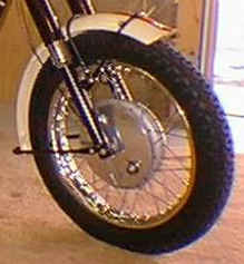
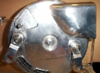
In 1967 the Triumph factory converted the
existing 8” (203mm) diameter full-width front drum from single leading
shoe (shown right, above, click for a larger view) to dual leading shoe with a
revised brake backing plate (or panel) for racing.
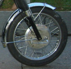
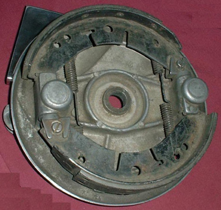
This brake (shown right, below, click for a larger view) became standard equipment on BSA and Triumph 650 twins and 750 triples 1968-70. There are minor differences: 1968 brakes had the cable entry at the rear of the backing plate, 1969-70 had top cable entry. A smaller 7” version was used on the smaller “C” range T100A, Daytona etc. and some BSA models 1968-74.
See my more specific comments on 2LS & 4LS brake design and function here:  . . | |
|
Each of the two shoes were operated by a separate cam and lever operating in the same direction. The cable sheath is
attached to a fixed mount on the backing plate, the cable runs to an
arm attached to the rear lever, an adjustable rod links the 2 levers,
and the front lever is in tension.
| |
|
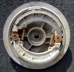
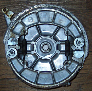
Conical brake
This brake was succeeded for 1971-72
on the triples and larger twins by a lighter “conical” drum assembly (so called because the drum is tapered in OD, with the larger end including the cast-iron liner) in the same diameter. The brake lining area is the same, but the lever operation follows a different
principle requiring fewer parts, less weight, and automatically
self-balancing. The cable’s outer sheath is fixed to the |
|
|
rear lever (rather than a
fixed mount on the backing plate) and the cable runs to the front lever. As tension is applied to the cable, equal and opposing forces cause the
sheath to push the rear lever and the cable to pull the front
lever.
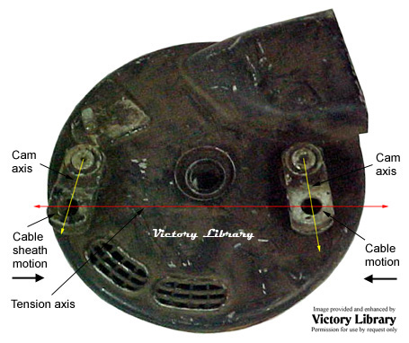
The conical is also considerably
lighter than the 68 style. Since the conical uses the BMW method of
opposing the arms: one arm has the cable end, the other has the cable
sheath, so the pull (red line) is always equalized between them under
tension. The cams rotate in opposite directions. The 68 has a single
cable arm and a link between the cams, which both rotate in the same
direction like most common brit and jap stuff. If adding length, the
new arms must be exactly matched for length - the new hole on the
same center vs. cam center. The extensions must follow the cam axes
(yellow lines). Click the picture for a larger image.
Conical brake modifications:
The original factory cable leaves something to be desired,
and that the compliance reduces the maximum effort applied to the cams
as well as using up lever travel without equivalent cam rotation.
However: the “self-balancing”method always
exerts the same amount of effort on both shoes, since even the partial
collapse of the cable sheath only affects its length before the 1st cam
lever, so the balance of force between the cams is not affected (although the adjustment is).
The cable “clocking” (orientation) is not
ideal in that it contains an un-necessary curve slightly backwards,
rather than point upward toward the bars. Applying tension to the cable
“uses up” some lever motion merely trying to straighten this curve. The
cable would be both shorter and stiffer if re-oriented.
Assuming that for purposes of both using the
original method of locking the backing plate to the fork slider and
keeping the air inlet normal to air flow that the original orientation
of the plate is to be retained, my next thought is to adapt a larger
diameter cable (which will require some modifications at both ends), such as the
nylon-lined clutch cable for the 1968-* H-D big twin, available from Barnett. This has very
low internal friction, the cable and sheath are very stiff and
lever-to-cam motion is much more linear. |
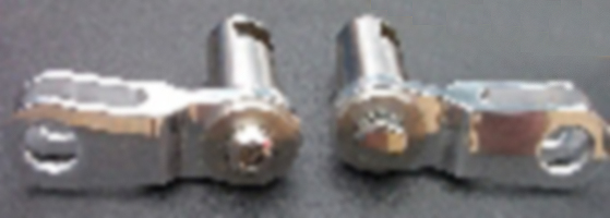
Conicals have been modified with levers lengthened to 3”. The fabricator took 2 pieces of flat steel strip stock, bent them, tig welded them together,
drilled the ends and had them plated. The original levers are
peened on and must be ground off, the brake cams drilled and tapped,
and the new levers bolted the modified cams. It was estimated that 2½” would also provide an advantage. In the picture above the cam levers are not parallel, but they will
become so, and the cable or sheath will be at the proper 90°
tangent for best mechanical advantage when the slack is removed and the
shoes reach their point of contact with the drum.
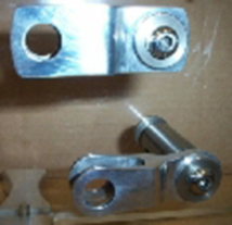
If you wish to extend the cam levers, the cautionary
note about following the existing centerline is not the only method. If
you’re very careful, the hole’s new positions could be offset slightly
towards each other to maintain the existing cable free length (i.e.,
hole center distance); otherwise the free length will increase, |
|
|
potentially requiring the sheath to be shortened. The hole offset will change the lever's mechanical advantage, so the offsets must be exact mirror images or shoe application will be asymmetrical. The ½” extended conical arms shown, right, are available from muttznuts. |
The adjustment is 1/2 turn of whatever the adjusting pitch is (26?). If it were critical,
I'd make an adjuster with finer thread or an eccentric bushing for 1
lever hole to be able to “de-slack” it so the motion of both arms was as
close to ID as possible.
When the 1971-72 OIF (“oil in frame”) bikes were designed by the former aerospace engineering team, most of whom had never ridden a motorcycle let alone designed one before, they strayed very far from common motorcycle practices in a lot of cases. From a dollars and cents (pounds in their case) point of view why not just use car brake shoes? The conical brake shoes were reputed to have been either modelled after, taken from or modified from a small British car. The slots are typical of car brakes and provide “handles” for automatic shoe adjusters, struts, and hydraulic wheel cylinders. |
Notice the slots in the shoe. Are they for expansion control? For compliance (viz. flexible to bend and conform to the
surface)? No other 2LS brake has this.
Could be, they don't make extra holes (= $$)
without a reason and getting the part cheaper works. But does the
slotting affect performance? If the shoes are ground (as they should
be), doesn't the flex allow them to conform 100% at the cam, and less
farther away as the braking effort increases? |
|
|
If this is correct, the shoes can be stiffened by
simply bridging the slots with a heli-arc bead (done quickly to avoid warping) before arcing the shoes to conform to the drum’ exact ID. |
There are some really obvious things that could be done with reasonable safety to test this, such as Plasti-Gauge
inserted between the shoes and the drum in several places, and a torque
wrench used to apply the cam to a specific load (× degrees of cam
rotation = Y ft./lbs. of torque from the hand lever) and see whether
the squish is different close to the cam, etc. My robust early Honda CB450 200mm brake shoes
(right) are cast in alumimum/zinc alloy and very stiff, note the reinforcing
ribs:|
|
| |
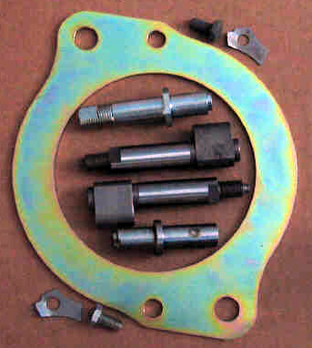
Norton |
Norton used 2LS until 1972-3. The factory offered this kit (available as 06-3410 from British Cycle Supply, click here to see their page: ) to improve the rigidity of the Commando dual leading shoe front drum brake based on a circular stiffening plate (”brake support plate”) and hardware to attach it to the existing backing plate, including replacement cams and posts with female thread to attach the support plate bolts. |
|
|
Since Norton used lever arms with a link in tension (as did the 1968-* BSA/Triumph), increased pressure can be had by simply extending the cable operating lever between the cam and clevis. The extended Norton arms, shown right, are available from muttznuts. Click the pictures for larger views. |
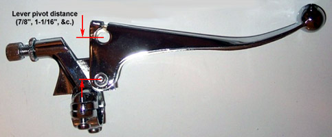
Handlebar levers |
British brake levers have been made in at least two variants as to the position of the cable receiver hole; there may be others. The “effective” lever length is not to the extreme end of the lever, since that isn’t the natural hand position, but rather to a point slightly inboard where the palm of the right hand would end. The ratio of the distance |
|
|
from this point to the lever’s pivot bolt to the distance between the pivot bolt and the cable end is the lever’s ratio or mechanical advantage. Levers are available with pivot-to-cable distances of 7/8” (22mm) and 1-1/6” (27mm), and may be interchanged provided the cable fits, slack adjustment is within range, etc. Click the picture for a larger view.
The effect of substituting the shorter (7/8”) lever for the longer is to multiply the mechanical advantage by the ratio .875:1.0625, or an increase of 17.6%. This reduces hand effort and cable movement to this degree.
The effect of substituting the longer (1-1/16”) lever for the shorter is to multiply the lever and cable movement by the ratio 1.0625:.875, or an increase of 21.4%. This increases hand effort and cable movement to this degree. There is no lever (or other component) that increases cable travel with reduced effort.
If your brake lever does not bottom out and stopping power is weak, try the shorter lever.
If your lever’s ball end touches the grip before full compression, try the longer lever. |
Inadequate stopping power
In addition to actual damage, inaccurate adjustment, severe lining wear &c. I’ve seen quite a few “inadequate” 2LS brakes of various brands that on closer inspection turned out to be:
1. aftermarket cable with spongy sheath
2. wrong hand lever
3. mis-routed cable with multiple “S” bends
4. lining very worn with radius much smaller than the drum OD
5. worn cam, bushing or shoe only making partial travel on application
6. drum “cleaned up” by removing rust only on the outer edge of ID, causing partial shoe contact
7. wrong linkage
8. reversed linkage
9. severe wear in the linkage clevis holes causing reduced motion on the slave cam, which converts
2LS to 1LS
All of these owners had examined the brake components carefully, but saw no broken parts hanging by a thread, and therefore assumed the poor results were a design flaw. |
See these other Victory Library booklets |

| 
| 
| 
| 
| 
| 
| 
| 
|

| 
| 
|

|

|
Triumph, BSA, Norton, A10, A7, A50, A65,
Lightning, Rocket, Bonneville, Tiger, Trophy, Super, Gold Star, Goldie,
Commando, Atlas, Dominator, Manx, AJS, Matchless, single, 650, 500,
750, 850, pre-unit, unit, british, Brit, Burman, emblem, badge,
Victory, panic, diamond
|