|
|  |
Here I will make various observations and comments on how the chassis, swing-arm, forks, brakes &c. function, and in some cases how to diagnose minor faults and make improvements. New material will be added regularly, and eventually better organized. Click below to jump directly to an individual topic. |
Engine mounting plates
Engine and/or transmission mounting plates to replace the original, adapt to another chassis, etc. such as a “Triton” conversion can be made of many materials. The major considerations are:
» Strength (resistance to fracture)
» Stiffness (resistance to bending)
» Weldable?
» Weight
» Cost
High-strength steel alloys such as “chrome-moly”, 4130, Reynolds 531, 4340 &c. offer no advantage in stiffness over mild steel, and are much more expensive, difficult to weld properly, must be heat-treated for proper strength and are in general not practical.
Aluminum weighs less than steel, and can be stronger for the same weight under certain conditions. However, it provides much less rigidity, which is necessary to maintain alignment between the sprockets, &c. If made stiff enough to match a steel plate (assuming they’re 1018 mild steel), the thickness must be doubled or tripled so the weight advantage is gone, although there is a modest increase in strength.
1/4, 5/16 & 3/8” thick plate is fairly cheap in odd shapes, certainly much less than the prices of pattern plates (although it’s a lot of work). Cut-offs and remnants are frequently priced above their scrap value based on weight, and generally much less expensive than pieces cut to size. For real savings look for pieces that have small holes, and engineer your design to incorporate them into the plan.
Extra care accurately spacing out the fasteners, alignment &c. is well spent since aluminum can only flex so many times before fracture (more much fragile than steel), and if it’s not stiff enough to remain shape-stable under stress it will eventually break. Some common choices of aluminum alloy are:
6061 is popular and relatively inexpensive for a structural alloy, but it isn’t really that strong. It is the strongest common alloy that is weldable, which makes fabrication easier. It doesn’t work harden very well, and is usually heat treated.
5052 is probably the most common wrought aluminum alloy. An H32 temper 5052 has lower tensile and yield strengths than 6061, but a higher fatigue strength. Since we’re talking about extreme vibration, that may make it more appropriate for engine plates.
2024, 2025 and 7075 are almost twice as strong as 6061, but much more expensive and not weldable in a practical sense. They don’t work harden very well, and are usually heat treated.
“Dural” is an aluminum alloy used by at least one manufacturer. Dural is a pretty generic name used by many manufacturers - usually European - for various aluminum alloys. The following is only if the HP30 designation has anything to do with US standards. ASM designations for heat treat use “H” for strain hardened alloys (wrought), “O” for annealed, “W” for solution aged, and “T” for heat treated. I don’t know what the “P” stands for.
“Fortal” is another common high-strength aluminum alloy, but not easily available in thin sections.
Titanium weighs less than steel, and is stronger for the same weight. However, again, it provides less rigidity and must be used in thicker section removing the weight advantage. It’s also expensive and difficult to form.
As of today, no composite (carbon, boron, &c.) material is practical for this purpose.
New fabricated mounting plates are easiest to fit if they match the original thickness so the fasteners need not be re-engineered. However, increasing the thickness for added stiffness and strength need not intrude into the fastener seat areas.
Even if you kept the original 1/4” &c. thickness at the mounting bolts “doubling” where possible with another (cosmetically ventilated?) 1/4” layer adds needed stiffness since twist, not shear, is the problem. The plates can be stiffened by the addition of a 2nd thickness overlaid on the actual piece, except for the mounting areas where more thickness will affect alignment or fastener length &c. (this may be on either side, depending on the design).
A stiffening rib can be welded, bolted or rivetted along the long axis to resist bending. For the most efficient use of weight and material, the rib should be short since bending will only occur near the center, and should be larger in either height, thickness, or both (a “V”shape) to provide the greatest stiffness at the center.
The weakest areas of the original plates are frequently the ends adjacent to the fastners, and the clearance holes for the generator, etc. There must be metal outboard of any fastener hole, but also the inboard area where the hole joins the plate must be as wide as possible since this area is highly stressed. To stiffen the generator hole, a simple ring with its ID fitting the the original hole exactly and the largest possible OD (probably tangent to the plate edge) can be welded, bolted or rivetted in place, and need not be cosmetically offensive if it’s between the two plates.
Any nuts used should be the largest diameter flanged type that will fit. Large, thick washers should be used under all nuts and bolt heads. |
Stiffening an existing frame
“Head shake”, as experienced by Kawasaki 30 years ago is where the forks violently slap from lock to lock in a “tank slapper”, ending in a crash. The worst case is where after a high speed run the brakes are applied:
1. weight transfers forward
2. the fork’s rake angle and trail are reduced
3. the forks collapse
All the weight is now on the steering head, which is almost vertical and has no rake or trail to keep it aligned. These things caused massive head-shake on the Z1, which somehow managed to get past the factory tests without being noticed, but spit off many riders even with street tires.
The cure was an assortment of pre-cut sheet steel gussets and small tubes which dramatically increased frame stiffness while only adding a pound or two to the weight.
Where rules and space permit, many production and even race frames can be improved by similar addition of extra cross-members, struts, gussets &c.
A gusset can be very effective if applied well, I just don’t know enough about it to tell what’s good and what looks OK but not effective.
The idea for design is to place welds/brazing in shear rather than tension (duh), so the “skin” should be sized and shaped to have a long axis at 90 degrees to the stress. Sometimes this isn’t possible and tension is all you can get, so a long join is needed here.
It’s important that the skin be flat and conform to existing curves very closely so that there is no slack (if it can move when the tubes are stressed it won’t add any stiffness until the slack is taken up).
I have various pieces of bar stock, drain pipe etc. to use as mandrels, use one slightly smaller than the frame tube to form a curve since the sheet will spring apart slightly as it’s formed.
Something recommended to me is to cut the skin longer than you need, weld a thick washer to the edge of the extra length, and use a wire cable through the washer and a turnbuckle to tension the skin over the tube while tacking in place. This is better than only using a clamp because it stretches the skin over any curves.
It’s important not to create a cavity than will catch and hold water, so no closed bottom without a drain hole at the lowest point with the bike on the stand.
What’s difficult is the thickness: if you use .020” it’s easy to form and bash into the exact contour of the existing tube structure, but not very strong and hard to weld since it’s much thinner than the parent tube.
When you go up to a known-safe size like .060” it’s easier to attach but very difficult to hammer form and much more “springy”. |
Forks
Coil spring rate
In general, the spring rate should (almost) completely prevent bottoming under the most severe conditions. Remember that this will vary with the course, and slightly with changes in chassis weight, tire pressure, air temperature, &c., and includes bumps plus hard braking. Under ideal conditions an observant rider will feel the lower slider just barely “kiss” the stop at only one point in the course, if at all. This is only safe where the fork’s internal design has a bottoming cushion, either hydraulic, rubber, &c. Where this is not known to be present no bottoming at all is safe. A spring with more tension than needed may cause the following problems:
1. the ride is unduly harsh, and the tire will skitter on rippled surfaces with loss of traction and understeering or wash-out.
2. only part of the possible hydraulic damping travel is used on a bump of fixed size, reducing effectiveness.
2. the damping effect will be masked, and cannot be accurately evaluated. |
Progressive springs:
“Progressive” means that there is more than one rate of delection in the spring, usually expressed in lbs. per inch of compression (how many lbs. of spring tension are needed to compress the fork for each inch of movement). This may be either:
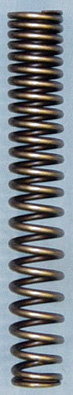
1. a multi-rate spring, most frequently by different coil pitch or vertical spacing (fewer coils per inch is stronger), but also possible by different coil diameter (smaller diameter is stronger), or different coil wire thickness (thicker wire is stronger) top vs. bottom. This may be either two or more discrete rates, a continuous change, or a combination of both.
2. multiple springs (usually two or three) with different rates stacked end-to-end. Shown, right, is a spring with multiple rate varied by coil pitch; click for a larger view. |
|
|
All methods offer the advantage of softer and more compliant ride quality and bump adhesion (low rate) while retaining good bottoming protection (high rate). A continuously varied rate is the most expensive to produce but frequently produces the best results. Multiple discrete rates in the same spring is also very effective, but both types require the entire spring to be changed to alter any characteristics.
Multiple springs can be made from the original spring suitably shortened, and a section from a different machine added to the same length. A small change in wire thickness has a very dramatic effect on spring rate; even 1mm will affect suspension behavior. For a small change, or a change to pre-load use an inner valve spring, although these are generally weaker than fork springs. A Harley-Davidson seat-post spring is very useful at .970” (24.6mm) diameter, and are available in various lengths and rates although all are fairly strong.
If the original fork does not bottom even on the bumpiest courses, the new section should be of lower spring rate, either smaller wire thickness, tighter vertical coil spacing, or larger coil diameter. The latter may not be practical, as the spring must fit the fork tube interior without contact for free motion - perhaps another 1mm or so is possible.
If the fork bottoms out despite additional pre-load, the new section should be of higher spring rate, either larger wire thickness, wider vertical coil spacing, or smaller coil diameter. This is less precise but far less expensive to tune. When shortening a spring, the preferred method is to saw or grind off a section while cooling the cut with water or oil. The cut surface is then ground flat to re-make the seating surface. If it’s cut with a torch the ends are no longer a spring but have been annealed. |
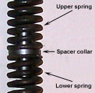
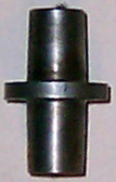
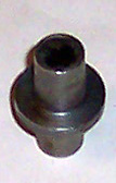
The springs can be aligned by a simple fabricated part; a thick washer with the same diameter as the larger spring and a large center hole as close to the size of the spring ID as possible separates the springs, and a short length of thick-walled tube or bar stock through the center hole and welded or brazed to the washer keeps both springs centered. | |
|
Some large valve guides are suitable. I have a spacer that may be of use, it’s 1.375” (35mm) long, the center collar is .875”” (22mm) OD and the center stem is .500” (12.7mm) OD, shown above right assembled in two springs.
For unsprung weight reduction the coils with tighter vertical spacing, larger wire thickness, or larger coil diameter go on top. The gram weight of 6” of spring is higher when the coils are close together - hence, less unsprung weight with wider coils on the axle. The upper (tight) coils will not move at all if the motion distance is short, reducing heat, whereas if the tight coils are below they will stack under a small load and the entire coil stack must move for any added motion. |
Hydraulic damping:
If the fork bottoms easily using a spring rate that is otherwise acceptable, try increasing the fluid viscosity by 1/3 to 1/2. If this does not help, try a small spacer above the spring to increase the pre-load (unless this increases the sag beyond acceptable limits). If still bottoming, the spring rate should be increased; use the next heavier spring you have, or what someone with the same fork and chassis is using as a test.
Not enough rebound damping? It was most noticeable in turns with a road surface that was a little wavy. That’s a big step between ATF and 30 - I’d try a few intermediates if you have the time. IIRC ATF is ranked down with 5 in viscosity, and fork oil is available in 5, 10, 20 etc.
Reducing fork twist
Lathe off some metal from the disc hub/carrier, move the rotor in a bit, move the caliper bracket over on the leg. Same brake torque = less leverage on leg.
Remember to allow for tire expansion from heat, “squash” from bumps, and fender clearance. |
Steering damper
The Busa/generic big Suzuki units, shown right, are cheap and plentiful - someone is going to make an adapter to common chassis if it works well. Click the picture for a larger view. | |
|
You need to know the stroke length of the damper before anything else. The position on the lower tree determines the mechanical advange vs. travel: closer to the fork tube = more travel and stronger; closer to the stem = less travel and weaker.
I would guess based on the weight of the Busa fork and wheel that you need less damping than the donor, so closer to the stem is probably a good start, but wherever you put it the piston must not stroke out at max travel or it will die (and lock the steering).
I would make the fork bracket with more than 1 hole to allow damping rate changes by moving the stud in or out. If the holes are at an angle (not radial) the OA length of the damper will not change so you won’t have to move the chassis mount.
Changing the clamp position changes both the OA length, and leverage, at once. Because the radius of rotation is small, the maximum change in leverage and travel is small (2 × the stud-to-tube center distance = 2-1/2”?). These clamps are designed to use a pre-selected damper with known (and suitable) characteristics.
This works fine if you make sure the OA length of the damper will span between the chassis bracket and farthest point of rotation of the fork clamp. As seen from above, it looks like 9 o’clock = shortest travel, then 6 o’clock, and 3 o’clock longest.
Once you have it attached, I’d try the 3 o’clock (outboard) position first and see if the steering is too heavy (high effort for small corrections = tiring). If yes, back it off by rotating the clamp inward (CW towards 6 o’clock) slightly and test. A Sharpie etc. line on the fork tube tells you where the clamp was for reference.
Stop when the effort is not irritating. If 3 o’clock has little effect you need more clamp offset to enlarge the center of rotation.
If you get all the way to 9 o’clock and it’s still uncomfortable you need reverse clamp offset, etc.
When it’s sorted a bit try a ripply curve that you know well and see if it’s more stable, etc.
Dampers: http://www.storzperf.com/jpgs/page22.html.
|
Hardware & fasteners
A hollow (gun drilled) or titanium axle will reduce unsprung weight slightly, but will not reduce rotational inertia.
Going to a bigger diameter axle both front and rear will help, such as ¾”or 20mm (.787”, a common Japanese size). This allows more tension on the nut, a larger clamping area to the fork leg or swing-arm, etc. In some cases a new hub bearing can be fitted with the same OD and larger ID to permit the axle diameter to be increased. Substituting a roller bearing for a ball bearing may be useful here. Although this increases axle weight, the purpose is added stiffness to the axle, and to the lock-up between the axle and the fork legs.
Axle spacers should be made of titanium or aluminum, hat-shaped (like a flanged tube), in the largest possible diameter for rigidity.
Every existing washer should be replaced by one as big an OD as will fit.
Rear axle spacers should be the largest possible diameter, with a big flat resting on inside of swing-arm axle plate for rigidity, washers welded to end of spacers. |
Fork crowns
The lower crown (“yoke” or “tree”) is frequently slotted where the fork tube transects it (some models have both crowns slotted), and this slot is then squeezed nearly closed with the bolt to secure the tube. It is extremely important that these bolts be tightened to spec, and that the slot is not closed - the sides should not touch at all with the bolt fully tensioned. This may indicate incipient failure at the slot and the crown should be replaced. A quick but imperfect remedy is to file or grind away a bit of metal so the slot sides do not touch.
If the crown’s threads are worn drill them out and use a longer fine-thread bolt and nut. In some cases enough metal is available to re-tap the crown to the next larger bolt for added clamping power; replace a 5/16” bolt with a 9mm or 3/8” &c.
If rules permit, a fork assembly with larger diameter tubes can be installed to increase lock-up to the crowns and bending resistance. Even a change of 1/8” may help, and larger diameter tubes are frequently made with thinner walls to save weight.
|
Fork brace
The fork tube (stanchion) is rigidly clamped in three places: the upper and lower crowns and the front axle. This gives a long unsupported distance, which invites movement and misalignment. If the tubes can skew (move out of parallel) they will bind up and refuse to operate smoothly. A brace added to or substituted for the front fender mount improves the fork’s resistance to twist and skewing. The brace should use all available mounting points on the lower legs; if a choice is available the widest pattern is preferable. The brace itself acts by increasing the rigidity of the tube lock-up at this point, so stiffness is the desired characteristic, not strength. |
Front brake torque link
A sharp angle right next to a point of attachment and connected to a long lever will flex with every brake application.
In addition, if the change mid-length in the lever is a twist to align with the air scoop, that will try to cock the backing plate and brake the arm at the fender mount.
This is a very easy piece to make if weight and space are not considerations: direct tension only, no bending forces (two studs with clevises and a piece of tubing, heim/rose joints shouldn’t be needed). If removing weight, this should be done only in areas that experience tension only - not near any anchor. This is why the point of attachment on the plate is generally at the same radius as the fork lug, and tangential pointing forward if not bolted directly.
For that fork and backing plate, IMHO a better design is a triangle with the shortest side the width of the two fork holes plus a generous distance to edge (3/4” minimum = ?). The two long sides are straight lines from the bolts to the backing plate location, so the arm is in tension from both points. If the plate mounting surface isn’t in the same plane (off-set, or skewed) this should be cured with a contoured stand-off permanently attached to the arm (not the plate) to mate the surfaces.
Remove weight by perforating the long axis of the triangle with holes, slots etc. at least 1” away from fasteners, both sides of holes countersunk and/or radiused.
A thick arm (3/8”?) with holes to reduce weight is preferred since there is always some side movement and it resists twist and bend better than a thinner plate.
If appearance doesn’t matter, a closed rectangular box (cheap on eBay) works very well but hard to mount - need to add tabs/brackets.
6061 is the best deal for the money, std. sizes on eBay are cheap.
7075 or 2024 is much stronger (= could be much smaller) but not weldable and considerably more expensive.
The reason why this is not done is because that places the arm in compression and must be much stiffer to work. If you want to use compression, just bolt or lock it to the leg - as they do, you don’t need an arm at all.
Part of it is compliance in the caliper - the casting isn’t as rigid as it looks. Part of it is the fluid pressure trying, with some success, to straighten out all curves in the lines - rubber, stainless or tube.
The only reason not to use steel Bundy tubing for the whole line is to permit wheel travel. The remaining flexible line should be as short as practical without producing a sharp bend at full travel.
The advantage to bolting a caliper to the trailing (rear) side of the fork leg is not brake torque control but reducing the moment of inertia of the fork’s steering travel by placing more weight at the center of fork rotation - the stem axis. The rear caliper location’s moment of inertia is the difference between the stem-to-fork-tube offset and the caliper bracket length, while the front location’s moment is the total of both. |
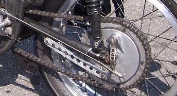
Rear brake torque link
A link is generally used to anchor the backing plate or caliper against rotation. This link can be in either direction in theory, but operating in tension is stronger, more reliable, and safer. A tension link is attached to the backing plate below the axle center, and runs forward. Heim (rose) joints are only needed to permit minor misalignment without cocking if the |
|
|
backing plate can move axially, but the link is attached to the swing-arm. If the backing plate is floated on a bushing or bearing and only rotates the link can be simply bolted in place. However, the forward (“dead”) end of the link will exert bending force on the swing-arm, which is why the link is generally long enough to almost reach the forward end of the swing-arm, which reduces the deflection. Click to see a larger view. |
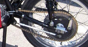
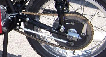
A better method is to “float” the forward end of the link as well, with a second Heim joint bolted to the chassis itself. This will affect the rear suspension under braking and the link is generally parallel to the swing-arm to minimize the effect, although alternate positions for the forward attachment bracket giving slight departure angle (non-parallel) will allow subtle changes in rear suspension for more tuning choices.
Below is the same link made adjustable with a simple fabricated bracket welded to the chassis at a conventinet point. The hole pattern should be a shallow arc to maintain link length in all positions. Click to see larger views. |
|
|
Rear shock absorber
Whenever practical inspect for damage: dents to the outer body; leaks; nicked or bent shaft; worn, stretched, or missing bushings.
It’s not uncommon for the exact length, pre-load, spring rate, fluid volume, damping rate etc. of two otherwise identical shocks to vary enough that you’re seeing each one try to make the wheel do something slightly different, and it’s most apparent when engine torque or brake load is added to the normal forces.
The easiest test is to reverse positions, and see if it feels any different.
To test the springs measure the overall free length and assembled height between the collars (OAL - pre-load = AH). Test the spring rate in lbs. per inch deflection by applying a known weight vertically to the end and measure the new length. E.g., if a 50 lb. weight compresses the spring by .600”, the spring rate is 1” ÷ .600” × 50 lbs. or 83 lbs. per inch. This is not practical on a dual, multi or progressive rate spring unless the spring is clamped at the rate change locus.
If the shocks come apart, drain and re-fill with a burette. Test each spring separately for pounds per inch deflection (add 100 lbs., measure how far is compresses, etc.).
To test the damping: remove the springs, place in a fixture vertically and attach a small weight to the top mount (a long bolt through the eye with stuff on both sides works). Time in seconds how long it takes to full compression with different weights, then compare both sides. The frame and swing-arm makes an ideal fixture since the frame can be supported with weight hung on the axle to test rebound damping, and inverted to test compression damping.
Substituting different shock bushings will affect shock behavior. Good rubber bushings can be stiffened by driving small nails or brads through them laterially, or weakened by drilling small holes through them laterially. This does not affect the actual rate of either the spring or damper, but makem effective at a small increment of wheel movement. Control is slightly improved but ride quality is always worse, perhaps to the point where the wheel skitters on anything but a pool table. Use 2 different rates if you wish with the stiffer one on top. An even stiffer method is to sculpt an automotive polyurethane shock or sway bar rubber bushing to fit, which has almost no compression but still damps vibration somewhat so is preferable to a Heim (Rose) joint or solid bushing.
|
|