|
|  |
Here I will make various observations and comments on how the chassis, swing-arm, forks, brakes &c. function, and in some cases how to diagnose minor faults and make improvements. New material will be added regularly, and eventually better organized. Click below to jump directly to an individual topic. |
Swing-arm construction
The swing-arm on older motorcycles is a simple pair of parallel or slightly divergent arms (generally round tubing) connected at the frame (forward) end with a tube containing the pivot shaft which rides on bushings or bearings. The opposite open end of the arms is closed only by the axle.
This forms a rectangle or mild symmetrical trapezoid, which offers little resistance to “racking” where the axle is forced out of parallel with the pivot. The unsupported length between the forward edge of the tire and the axle center is very weak, the leverage exerted by the tire’s contact patch against the arms is extremely high, and the arms cannot remain parallel under any sort of high cornering force.
Increasing the strength of the arms (thicker wall tubing, 4130, etc.) have little or no effect here. The problem is stiffness, and extending the depth (top to bottom distance) of the structure is the best cure. This may be done by several methods:
A. Substitution of a larger diameter round tube. This also increases stiffness in the other planes. |
B. Substitution of an oval tube oriented with its long axis vertical and the same width (short axis) as the original to minimize fitment difficulties. This also saves some weight over Choice A. Here’s a replacement Norton Commando by Clubman Racing; notice the increased height to add stiffness without restricting tire size. Click for a larger view. |
|
|
C. Addition of another similar tube in parallel but vertically spaced slightly apart and joined at both ends. Another version simply adds a piece of steel strap positioned vertically above or below following the contour of the arms and pivot tube, and welded in place. Easy to design and somewhat better than the original, but wastes weight by use of ineffective shape.
D. The most effective method is to add another member to the existing structure to make its height 3-dimensional. The new member is the brace and its attaching struts. The concept is a variant of Choice C. above, except that the forward end of the extra tube is rotated, and a strut connects this end to the pivot tube. The new shape is a triangle in elevation.
The brace also permits a strut to connect the original arm’s unsupported length to the brace which greatly increases the bending resistance of both, which varies as the cube of the unsupported length. If the strut interrupts the main arm’s length in mid-span, the bending resistance of each half of the arm becomes 800% as stiff: |
ΩB = 100 ÷ N³ |
where “ΩB” is the change in resistance to bending (as a percentage of the original arm), “N” is the new span length (as a percentage of the original arm length) and “³” is cubed (3rd power).
If the strut is positioned elsewhere along the arm for reasons of convenience the change is still dramatic; use the same formula to determine the improvement. For example, a 40-60 split yields increases of 1,562% and 463%, respectively. A 1/3-2/3 split yields 2,701% and 337%, respectively. Even a 25-75 split yields 6,400% and 237%. From this we learn that additional struts to stiffen the span are generally a waste of effort, and two struts per side is sufficient for this purpose in almost all cases. |
AHRMA rules
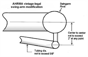
AHRMA’s popular “Formula” and “Sportsman” vintage classes permit a limited swing-arm modification, where a brace of specific size is attached to the existing structure and is grandfathered in as a “period modification” based on its historical use by Big D Cycle in 1971 (2007 Rules: 9.7.3). The mechanical requirements are shown, right; click to see a larger view. |
|
|
Clearly, the limits given are important: the diameter of the brace, and the vertical depth of the swing-arm as modified. Increasing either (or both) of these dimensions will result in an significantly improved (but illegal) component. A 3/4” brace and 3” depth will still fit many chassis, which is why it’s not permitted.
Please note that there are no prohibitions of the forward point of attachment of the brace to the swing-arm, the separation angle of the brace relative to the arm, the number or size of vertical struts connecting them, or the width across the brace. From this I deduce that these have, relatively speaking, little or no effect on handling or structural integrity, and may be designed and applied to best suit the chassis. |
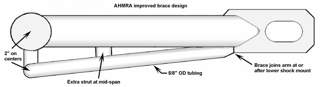
I propose a brace that conforms to the AHRMA rule, and provides maximum efficiency with minimal construction time, minimal welding, and low number of fabricated components. The depth, measured between the center of the pivot tube and the |
|
|
center of the brace is 2” and the brace diameter is 5/8” as required, but the struts connecting the brace at the pivot tube are enlarged to 5/8”, and a 5/8” vertical strut are also added at mid-span to shorten the main arm’s unsupported length; click to see a larger view. |
Minor modifications
An extra cross-piece connecting the left and right main arms has a positive effect without making the “footprint” of the arm more intrusive into the chassis. The cross shortens the “leverage” of the axle against the pivot bolt tube, but only to a limited extent.
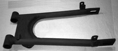
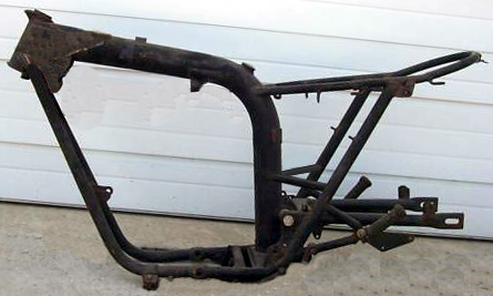
If adding a cross-piece parallel to the pivot it should be at least as tall as the arms, as close to the tire as safe (allow for expansion 1/2”?), and in shape a box as deep (front to back) as possible, 1/16 to 3/32” wall (or the same as the arm) is enough for results. Inlet the ends to fit the arms closely before welding, which must be done in a fixture - especially on a Commando. For best clearance the rear face of the box facing the tire should have a concave curve matching the tire radius. Shown, below right, is a 1971-* Triumph B Range and BSA twin “oil-in-frame” swing-arm in standard form, and with the cross piece extended and re-curved. Click either picture for a larger view. |
The Triumph/BSA oil-in-frame design is fairly good in standard form, but there are areas where improvements can be made.
The swing-arm has two separate loops rather than a continuous tube to accept the pivot shaft. The shaft is supported between these loops by a center loop attached to the frame’s backbone (oil reservoir), and by one loop on each left & right angled frame rail. Under hard cornering, especially with sticky tires, the center loop cracks and eventually tears away. |
|
|
Line-boring the existing loops (viz. reaming through all five points simultaneously to keep alignment) will add diameter only to the extent that you reduce wall thickness. I don’t know if the current wall thickness is overkill, just fine or not sufficient so I would hesitate to reduce it, especially since the increase must be small - certainly 1/8” would be too much.
The other method is to make new bushings with the same OD (= loop ID) but thinner wall. A bushing will be thinner than a needle for the same load capacity, and the difference is the shaft OD increase. I’m not sure how thin is safe - again, you won’t get much.
The pivot shaft needle bearing is one of those “looks like a good idea” that doesn’t work. The original bushing is generally either self-lubricating (“Oilite”) or has a gease fitting nipple, but has far higher load capacity than a needle, and doesn’t require a specific minimum surface hardness (or finish) to run on.
There is also no gain to be had in any event - the swing-arm pivot does not rotate in the bearings but only oscillates a few degrees, so the difference in friction is too small to matter.
A needle bearing is designed to run only on a hardened and smooth surface, and will brinnel even this eventually. Since the contact sweep area is very small (30°?, or 1/12th of a circle), the pivot will develop small depressions only where the needles pass over them. Each needle only traverses a small fraction of an inch of pivot surface (rather than average the wear out over the entire circumference, as would be the case if there were rotation).
The needle bearings have no thrust (end play) control, so the lateral load must still be controlled by bushings. Harley-Davidson swing-arms (since 1952) use Timken bearings, which control both radial and end thrust but are larger, heavier and more expensive.
I’d like to see a big change in OD like 25% or more. Obviously, use some existing shaft with the right diameter and too long, then buy the bushings, and make the loops to match the bushing OD so you only need fabricate the loops and mod the pivot.
E.g., a 1.00” OD × 12” long solid shaft stiffness is about .049 and weighs 2.67 lbs. A 1.50” OD hollow (3/32” wall) shaft stiffness is about .103 (more than twice as stiff) but only weighs 1.41 lbs., or 47% less (although the loops etc. will add the weight back). The loop attachment to the swing-arm and frame will also be stronger with more area at the weld points.
If, as I suspect, the pivot shaft may be bending with swing-arm roll* to tear off the center loop a bigger shaft will help, but the frame ears where the loops attach still should be improved. |
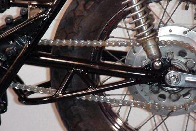
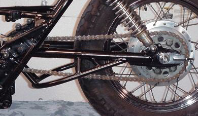
My first guess is that the existing ears are bending in and out (skewing) with the pivot shaft. If so, bracing/gusseting them to their frame rail won’t do much; they need to be anchored at an angle. If there’s room run a tube or triangular gusset from the inside of the ear just outboard of the loop down at an angle to the bottom of the frame where the backbone seats. This is why you see a horizontal strut running |
|
|
from each angled tube above the ear inward to the backbone, but there isn’t always room and it’s visible, as shown here. Here’s an OIF with this mod, click the image for a larger view.
The usual rule is: mentally project your new frame member. Is it parallel to any part of the structure it’s attached to? If so, it will form a trapezoid under stress (the corner angles will skew away in opposite direction and become more acute & obtuse). Instead, re-position at least one end to make a triangle, which is less subject to shape deformation under load. |
* I use aircraft/sports car terminology to identify movement:
”Pitch” is up and down movement on the length-wise axis of the wheelbase, like normal suspension motion. Frames generally resist this fairly well.
”Roll” is rotation around the same axis, like when you bank for a turn; also caused by shaft-drives, counter steering, etc. If the frame and swing-arm do not roll at the same rate bending or breakage occurs at the weakest point. Many good frames are very weak in this plane, especially at the steering head and swing-arm pivot.
”Yaw” is rotation around a vertical axis, like major oversteer or intentional slide in flat track. Sideways bending is typically not a problem. |
If your racing rules permit (or you don’t care) more stiffness can be added by increasing the height dimension on the intersection of the arms, pivot tube and braces. A simple triangular piece of 1/8” steel plate held vertically bridging the join across the arm and pivot tube from below on each side helps a lot, but be sure it doesn’t contact anything at full travel. Since it’s close to the pivot it has almost no unsprung weight. The swing-arms weight is sprung vs. unsprung in direct proportion to the placement of each section in the length between the pivot bolt and the axle.
The usual method (a full length brace) wastes weight since the torque near the axle is almost nothing.
You can replace the arms completely with oval or elliptical tubing with about the same thickness but twice as tall.
Easiest fixture: two steel bars, one is the pivot OD, one is the axle OD, but 2 feet long to give leverage and clamped to a big fixture, parallel with a bubble level, etc. This is also the time to consider whether you want a different length.
Brace design and construction
The individual design elements of a braced swing-arm must, of course, be part of a comprehensive design, but they may evaluated separately to make the process less complex.
1. The first consideration, which must be resolved before anything else can be done is: “is this the length I want to use”. If so, the shock mount need not be disturbed, unless you wish to re-locate or strengthen it. More about added length here:  . .
2. The next step is to map out the limits of suspension travel to determine where the brace will interfere with the center stand, chain run, chain guard, exhaust system, etc. This is best done with the motorcycle supported so that the rear wheel is suspended and the shocks are topped out. Make a diagram, and measure from the closest part of the swing-arm to anything close, including the frame ahead of the wheel below the swing-arm. The maximum brace size must be at least 1/8” smaller (I prefer 1/4”) at all points to allow for shock rubber compression, tire squat, deflection etc.
3. How thin should the brace be both in diameter and wall thickness, how far back it should join the main arm (farther back looks like a good idea but useless unless you suspect the axle slots - which is quite a different problem), where the struts should be, material to use, and (very big) how far down the brace should be at maximum. My opinion is that the brace should be as “deep” as possible, even if it means making a window for chain clearance between the arm and strut because the arm/strut/brace triangle is the single biggest factor.
4. Where should the brace be mounted? It may be located either above (as in modern motorcycles) or below the swing-arm.
The top mount offers the advantage of incorporating the existing monoshock support and rising rate linkage, which don’t exist in vintage British machines. They could be incorporated, but this would not be legal for any vintage racing and require completely re-engineering the chassis - not just adding a few bits.
The bottom mount is in tension and is therefore slightly stronger, intrudes less into the existing components, and has little effect on ground clearance if properly designed. Even though the amount of tubing, welded area, quality of construction etc. may be otherwise identical, a bottom mount is stronger. Think of it this way: a top mount is a column supporting a load; to resist bending it must be very stiff. A bottom mount, in tension, requires much less stiffness in the area between the rear axle and the center strut, only sufficient strength to prevent separation, and almost anything (1/8” thick, 1” wide strap like a brake torque link) will do that. The brace area between the center strut and the pivot tube must, of course, still be very stiff. You have a choice: save a few ounces by using smaller tubing for the brace, or get some extra rigidity as a bonus with the same dimensions.
Factors in tube choice for stiffness, ranked in order of descending effect (assuming that length is fixed):
1. tube diameter
2. material
3. wall thickness |
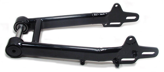
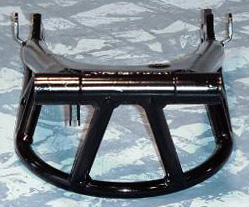
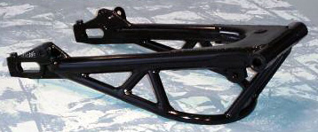
Here’s a round-section swing-arm (the actual component is from a Yamaha XS650, but the construction is very similar to common British pieces) greatly improved by the addition of a 3-dimensional brace, click for a larger view. This is simple to design and inexpensive to make, although alignment and attachment must be precise. |
|
|
This will require clearance checks for the center stand, footpeg mounts, exhaust system hangers, etc. Be sure to measure the entire travel of the swing-arm.
This one was done by joe-wiseguy of “wiseguys-choppers-and-customs”, click here to visit their eBay store: . Notice that the brace is below the swing-arm so that it acts in tension. The nose is angled forward to give clearance to the frame when the shocks are extended. The brace does not extend all the way to the axle - it’s not needed since the twisting force there is much less, and the weight at the axle is almost 100% unsprung and should not be increased. This is not a legal mod for AHRMA, sorry - that’s how well it works.
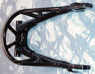
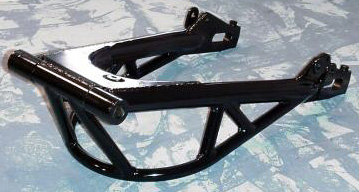
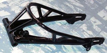
Here are some additional views of the braced swing-arm to show the detail. Click on any to see a larger view. |
Swing-arm length
The swing-arm’s length, measured between the pivot shaft and the rear axle, is an important function of handling not only as an absolute but as a proportion of the wheelbase. Simply extending the swing-arm adds roughly the same amount to the wheelbase since the “at rest” or normally loaded position is approximately horizontal. Shown right is the same Yamaha swing-arm extended slightly. Click to see a larger view. | |
|
More swing-arm length has the following effects:
» The center of gravity moves forward, loading the front wheel.
» The turning radius is increased and turning is slower.
» Weight transfer forward on braking is reduced, the rear brake does more work.
» Weight transfer backward and traction on acceleration are reduced.
» The swing-arm arm is less rigid due to increased span length.
» Clearance to the inside of the rear fender and support loop is reduced.
» The brake torque link and chain guard must be extended, and links added to the chain. In
extreme cases a tensioner should be added to the lower chain row.
The shock absorber & spring presents its own problems:
If the extra swing-arm length is added rearward of the lower shock mount (usually the easist method, since it avoids re-locating the shock mounts):
» The spring and hydraulic valve rate becomes effectively weaker, because leverage against the
shock is increased.
» The shock’s travel (and therefore the maximum suspension travel) is slightly reduced.
» The rear wheel’s positions (droop, loaded, and full compression) are all slightly higher, the
chassis and seat are slightly lower, and a small amount of rake & trail are added to the steering.
» Due to the forward inclination the suspension becomes slightly “rising rate”, where the rate per
inch of travel increases as the compression limit is approached.
|
See these other Victory Library booklets |

|

|

|
|

|

|
|

|

|

|
|