|
|  |
Here I will make various observations and comments on how the chassis, swing-arm, forks, brakes &c. function, and in some cases how to diagnose minor faults and make improvements. New material will be added regularly, and eventually better organized. Click below to jump directly to an individual topic. |
The frame |
The purpose of the frame, aside from the obvious utility considerations, is firmly to join and align these elements:
1. the fork stem; secured by the steering head tube and its surrounding members
2. the power source; the transmission output sprocket supported by either the rear of the engine case
(unit construction) or transmission case (non & pre-unit construction) and its mounts
3. the swing-arm pivot; secured by the cross-tube |
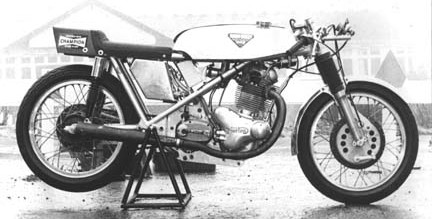
This is the “load path”, and if this is deflected by application of power, traction, etc. handling deteriorates. Frame members that do not fulfill this essential function are ancillary and need not be overly rigid. A classic example of a (more or less) direct load path is the Colin Seeley frame and its variants, a Norton is shown here. Notice the straight line from the steering head to the swing-arm pivot tube; click the picture for a larger view. | |
|
The distinction between “functional” and “broken” was the standard applied to many structural bits back in the day: did it break? If not, use it. If so, add material where convenient and cost-effective until it stops.
Since then, another critical benchmark has been interposed: it doesn’t break, but does not maintain its exact location, alignment, shape and/or dimensions under stress, and will not perform as expected. Strength is frequently not the test, but rigidity (stiffness). The forces exerted on these parts is far greater than anticipated by Turner, Page, etc. who were always working under constraints of cost and weight in any case.
This higher standard includes frames, swing-arms, fork clamps, fork tubes, axles, cranks, head, cylinder and crankcase castings. Most of these do not have enough stiffness to prevent compliance (yielding its designed shape to applied force), and benefit from added bracing, methods of applying load over a larger area, etc. |
Analysis of an existing frame |
In theory, any frame can be improved by the addition of cross-members, gusseting tube intersections, larger fasteners &c. There is no specific guide to detect inherent weakness in a frame design, but in general any street frame built before 1970 needs work, excluding Featherbed types used entirely for pleasure. How to determine where existing areas need improvement:
» Any long unsupported tube, including the top rail, &c.
» Any open area bounded by tubes forming a rectangle or trapezoid
» Any curved tube
» Any bracket with its fasteners not in double shear
Look at pretty much anything made for the street more than 10 years ago (except BMW, Buell, Ducati and Guzzi). Such an easy lesson, and took 50 years to learn. Even those need dampers, partially because they don’t rely on high rake and trail for stability since the frame does not move under stress.
That’s what a “great handling” frame does: keep the steering head in exactly the same juxtaposition with the swing-arm mount under all conditions, nothing more nor less. Except for the difficulty of fitting the engine and rider afterwards, a stock whoozit flexi-frame could be made just as effective by simply welding tubes all over it - it’s not magic, it’s just physics.
Construction & modification
Straight tube is easier to work with, no worries about kinking a bend, ugly multi-radius bend, or making 2 side mirror images.
Also stronger if properly triangulated - any bend at all is going to bend again when stressed, whereas a triangle can only flex out of plane (unless the weld breaks).
It’s easy to underestimate how stiff the frame needs to be for anything other than dirt, since almost no British traditional frames had enough structure especially at the steering head and swing-arm perch. Look at a Buell, Moto Guzzi, Ducati etc. for an example of how much metal is needed to make the stem-to-rear wheel placement really solid.
Stiffness
A chassis that is not stiff enough permits some movement (“compliance”) to occur within what should be a completely rigid structure. Since this is not linear nor controllable, it modifies wheel motion reacting to the suspension, and causes irregular handling. Compliance is generally caused by power transmission to the chain, the rear sprockte’s torque reaction to power, lateral twisting of the frame from chain load, and bending of the steering head and/or swing-arm pivot from cornering traction.
Years ago, improvements made to frames to correct breakage increased stiffness to the point where the spring rate was now too high and caused chattering and loss of traction - hence, the belief that “the frame should move a little”.
A more rigid chassis has another benefit: a softer suspension rate giving better comfort and more accurate wheel tracking on ripply surfaces.
The easiest way to add stiffness in terms of engineering is also the hardest to actually construct. The stiffness (not the strength) of a tube of fixed length depends on these factors, in descending order:
1. diameter
2. shape (straight = best)
3. material: mild steel is fine, chrome-moly is no advantage, and titanium and aluminum are worse
4. gussetting and braces
5. wall thickness
As you can see, the highest priority is the largest tube you can fit on the bike, but this is limited by engine size, gas tank saddle opening width, controls, cosmetic choices etc. The difficult part is leaving room for the go-bits and the pilot, have it weigh as little as possible, and cost even less.
This is why a big “backbone” containing oil or gas is used - it won’t move. The Norton Commando frame’s with its 16 gauge 2.25” OD central tube is the poster child. Generally, going to 1-1/4” is easy, and a big step up from the usual 1” to 1-1/8” since the stiffness is proportionate to the 4th power of the diameter. 1-1/4” tube with .069” wall thickness is 166% as stiff as 1” tube @ .090” wall, and weighs slightly less.
Wall thickness
A dent, deformation, puncture &c. to the tube wall will potentially cause catastrophic failure, especially if near the center of the span. Thin wall also invites vibration fracture, and easy penetration by an intersecting tube or other component. The usual rule is that the wall thickness should be at least 2% of the tube OD, but in my opinion 1/32” (.031”) is the thinnest I would use.
Shape
Round or elliptical tube is not the only choice. Square or rectangular tube can be used with the obvious fitting difficulties and cosmetic disadvantages.
For the same nominal size (round tube OD vs. square tube width) square tube is stiffer if its diagonal plane is the stressed axis. Simply rotating the tube 45° so that its greatest dimension becomes its stressed axis greatly increases its bending resistance. This is due to its diagonal width being greater than its lateral width by about 41.2% (H = W ÷ Sine 45°, or H = W × Arc Sine 45°). A 1” round tube is, of course, 1” at all points, but a 1” square tube is actually 1.4142” measured through its 45° axis. Stiffness is calculated by (1/12) ×((D^4)-(d^4)), where 1/12 = .083333333, “D” is the nominal outside width and “d” is the inside width measured across the flat sides, and “^4” is the 4th power (exponent) of the dimension. Since the relative size of this axis (proportionate to the original dimension) is known, the increase in stiffness can be calculated from the relationship without knowing the specific dimension. The math: 1.4142^4 = 4. The tube’s bending resistance in its new orientation is 400% of the “normal” position, or an increase of 300%.
There is a weight difference: a round tube weighs less than a square tube of the same nominal size, but more than a square tube with the same maximum (diagonal) width. The stiffness to weight ratio of the square tube is higher.
In some frames the width across the chassis is limited, but the depth (height) is not, and a square (or better) a rectangle with its long axis vertical with the same lateral width as the same size round tube will add stiffness here.
A tube with an asymmetrical cross-section such as an ellipse or rectangle is stiffer through its long axis roughly proportionate to the ratio of the axes, so proper orientation is needed to align this axis with the anticipated bending force to achieve full benefit. To calculate the stiffness in this plane, use the longer side of a rectangle or the major axis of an ellipse.
Click here to see compare tubes of the same wall thickness but different OD for a huge change in stiffness but almost no weight penalty:  . . |
Once modified, the frame has almost no original value (except for your project), and finding someone competent to do the work will not be easy. The areas that need work are highly stressed, and the fabricated parts should not only be inserted into the remaining tubes as far as the curve permits, but insertions are usually pinned with a small rod through both, or rosette welded through access holes in the tube OD. This should be done in a frame jig to reduce distortion, or heavily clamped to a big I-beam etc. If you don’t care how it looks, I would gusset the joints as well.
Unless you KNOW that the weight saving occurred in non-critical areas and produced no additional compliance or mis-alignment under load, 5 lbs. is a small penalty to pay for removing 1 variable from the equation (“I don’t need to examine this again”). The bike + rider + fluids still weighs over 450 anyway, and money spent can save weight elsewhere.
Simple things left un-done: nuts used in simple shear (no tension, just a locator) can be about 1/2 thickness, but they generally used common industry height to avoid production line errors and expensive purchase of specialty bits. Many axles and fork stems can be drilled easily, and are longer than needed if safety wire is used. Big chunks of mounting plates are structurally useless and can be cut with a hole saw if you know where; after a little exposure, you can intuitively guess pretty well where a plate is going to bend or break. A simple plastic moto-x inner rear fender weighs nothing even compared to an alloy and is invisible, but it's not “cafe”. Many other small thermo-plastic bits such as chain guards, chain guides are available cheaply for moto-x. Really simple way to stiffen an older fork: weld the tubes together with a box-bridge just above the bottom-out point. It takes more work to re-assemble, but still can be serviced etc., the clamp and axle make a fair jig, and the bridge is far more rigid and lighter than a bolt-on brace.
Yoshimura once sold a kit of slightly oversize bolts for the engine-to-frame for the Z1/KZ900 - ream the hole oversize (original = metric, they just substituted aircraft bits in fractional, 8mm > 11/32” = +.029”, etc). and use the case as a stressed member. Even then, the full benefit wasn’t realized: the hardware should consist of a bolt (not a stud) with a very large thick captive washer on the closed end slightly larger than the maximum seating surface of the engine or frame. The open end has the nut welded/brazed to the washer to make a “hat”. The larger rigid seat increases the stiffness of the joint quite a bit with almost no weight penalty, but must be individually fitted.This is excellent for both axles and swing-arm pivot as well. |
Featherbed, Manx, &c.
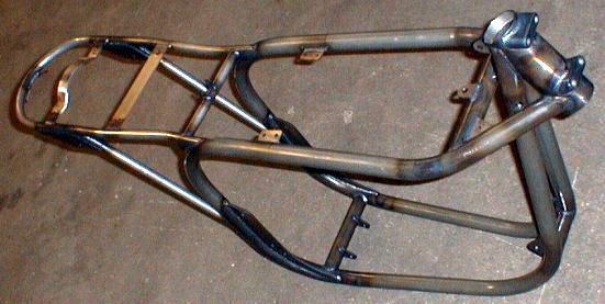
These are very nice, look at the structure around the steering head, not only the amount of tubing but the 3-dimensional effect with support for the fork stem in 3 planes. The biggest change from the more traditional British frame is that the top tubes splay off from the steering head very widely, so the steering head and fork stem are tied down in both planes. Here’s a generic Featherbed replica, click the picture for a larger view. | |
|
Considering that almost all the ones I’ve seen for sale needed straightening, minor dent and rust repair, tabs and brackets restored or added, stripping, painting they are not really a bargain, especially since they improve handling only when compared to the stock whatever. I’ll bet money that a bar through the steering head and another through the swing-arm mount could be rotated against each other quite a few degrees with less effort than you would like. If you want a “period piece” to restore your errant youth, go for it. If you just want a chassis that works there are cheaper choices.
The Manx enjoyed a weight saving from use of Reynolds 531 tube instead of DOM, and the street bike was probably made to the same dimensions but cheaper material to save money, and we know now what they vastly underestimated then - that even such a small engine will stress the frame beyond acceptable limits.
|
1971-* BSA & Triumph
Other than weight (and a few unsightly bits you can remove) the OIF is a good frame, the big top tube adds a great deal of stiffness which is generally under-estimated as to necessity for pavement. |
Buell
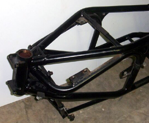
The older “tuber” frames use “iso-lastic” design with the entire engine & (unit) transmission + swing-arm mounted in rubber with heim links for control. The main tubes are 4130 chrome-moly, 1-1/8” diameter. Here’s a view showing the truly massive steering head area; notice the similarity in concept to the Featherbed but with generally larger structure. It’s also almost new rather than 40 years old, and priced a bit below a Featherbed - I paid $75.00 for this 2000 Cyclone. Click the picture for a larger view. | |
|
|